Nissan Sentra Service Manual: System description
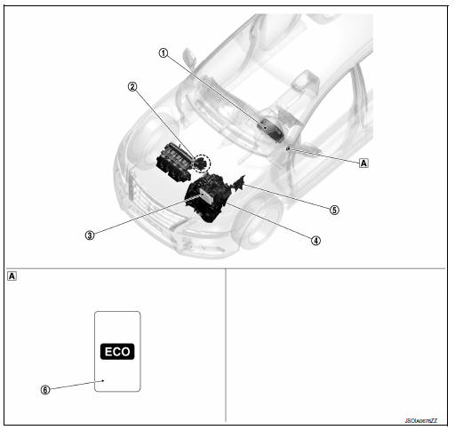
Component parts
Component parts location
 Instrument lower finisher
Component description
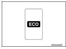
Eco mode switch
- The ECO mode switch is installed to the instrument lower finisher.
- When the eco mode indicator lamp on the combination meter is off and the eco mode switch is pressed, the eco mode is active and the eco mode indicator lamp is on.
- When the ECO mode indicator lamp on the combination meter is ON and the ECO mode switch is pressed, the ECO mode is cancelled and the ECO mode indicator lamp is OFF.
Eco mode indicator lamp
Design/purpose
The eco mode indicator lamp inform the driver that the vehicle is in eco mode.

Bulb check
Not applicable
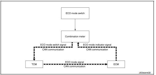
Signal path
- TCM receives ECO mode switch signal (ON/OFF) from combination meter via CAN communication. Based on the signal, TCM transmits ECO mode signal to ECM via CAN communication.
- ECM transmits ECO mode indicator signal to combination meter via CAN communication. Based on the signal, combination meter illuminates ECO mode indicator lamp.
Lighting condition
When all of the following conditions are satisfied.
- Ignition switch: on
- The eco mode switch is pressed when the eco mode indicator lamp is off
Shutoff condition
When any of the condition listed below is satisfied.
- Ignition switch: other than on
- The eco mode switch is pressed when the eco mode indicator lamp is on.
- The SPORT mode switch is pressed when the ECO mode indicator lamp is ON.
System
Eco mode control
Eco mode control : system description
System diagram
System discription
- Tcm receive eco mode switch signal (on/off) from combination meter via can communication. Tcm transmit eco mode signal to ecm via can communication according to the signal.
- ECM transmit ECO mode indicator signal to combination meter via CAN communication. Combination meter illuminates ECO mode indicator lamp according to the signal.
Each ecu control
- For tcm control, refer to tm-104, "eco mode control : system description".
- For ECM control, refer to EC-52, "ECO MODE CONTROL : System Description".
 Precaution
Precaution for supplemental restraint system (srs) "air bag" and "seat
belt pre-tensioner"
The supplemental restraint system such as “air bag” and “seat belt pre- ...
 Ecu diagnosis information
Eco mode
List of ecu reference
...
Other materials:
Front combination lamp
Exploded view
Large cover (not serviceable)
Small cover (not serviceable)
Front combination lamp
Halogen lamp bulb (high beam)
Turn signal lamp bulb
Turn signal lamp bulb socket
LED harness connector
Halogen lamp bulb (high beam)
harness connector
Halogen lamp bulb (low b ...
Wheel side
WHEEL SIDE : Removal and Installation
REMOVAL
Remove the wheel and tire using power tool. Refer to WT-47, "Exploded
View".
Remove the brake caliper torque member bolts, leaving the brake hose
attached. Position the brake caliper
aside with wire. Refer to BR-41, "BRAKE C ...
Control cable
Exploded View
Control cable
Lock plate
Transaxle assembly
Bracket A
Bracket B
CVT shift selector assembly
Manual lever
Grommet
Removal and Installation
INSTALLATION
CAUTION:
Always apply the parking brake before performing removal and
installation.
Apply the p ...
