Nissan Sentra Service Manual: System description
Component parts
Component parts location
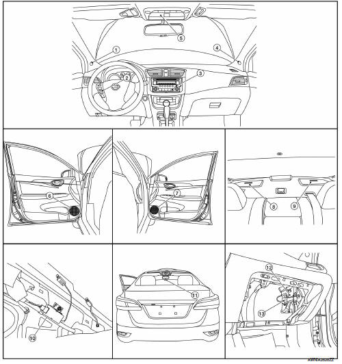
- Front tweeter lh (if equipped)
- Steering switches
- Audio unit
- Front tweeter rh (if equipped)
- Microphone (if equipped)
- Front door speaker lh
- Front door speaker RH
- Rear speaker rh
- Rear speaker lh
- Antenna amp.
- Window antenna
- BluetoothВ® control unit (if equipped)
- BluetoothВ® antenna (if equipped)
Component description
System
System diagram
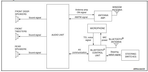
System description
Audio system
The audio system consists of the following components
- Audio unit
- Front door speakers
- Front tweeters (if equipped)
- Rear speakers
- Steering switches
- Antenna amp
- Window antenna
When the audio system is on, am/fm signals received by the window antenna are amplified by the antenna amp. And sent to the audio unit. The audio unit then sends audio signals to the front door speakers, front tweeters and rear speakers.
Refer to owner's manual for audio system operating instructions.
Hands-free phone system (if equipped)
System operation
Note:
Cellular telephones must have their wireless connection set up (paired) before using the bluetoothВ® telephone system.
The bluetoothВ® telephone system allows users who have a bluetoothВ® cellular telephone to make a wireless connection between their cellular telephone and the bluetoothВ® control unit. Hands-free cellular telephone calls can be sent and received. Some bluetoothВ® cellular telephones may not be recognized by the bluetoothВ® control unit. When a cellular telephone or the bluetoothВ® control unit is replaced, the telephone must be paired with the bluetoothВ® control unit. Different cellular telephones may have different pairing procedures, refer to the cellular telephone operating manual.
Refer to the owner's manual for bluetoothВ® telephone system operating instructions.
BluetoothВ® control unit
When the ignition switch is turned to acc or on, the bluetoothВ® control unit will power up. During power up, the bluetoothВ® control unit is initialized and performs various self-checks. Initialization may take up to 20 seconds.
If a phone is present in the vehicle and paired with the bluetoothВ® control unit, nissan voice recognition will then become active. BluetoothВ® telephone functions can be turned off using the nissan voice recognition system.
Steering switches
When buttons on the steering switches are pushed, the resistance in steering wheel audio control switch circuit changes, depending on which button is pushed. The bluetoothВ® control unit uses this signal to perform various functions while navigating through the voice recognition system.
The following functions can be performed using the steering switches:
- Initiate self-diagnosis of the bluetoothВ® telephone system
- Start a voice recognition session
- Answer and end telephone calls
- Adjust the volume of calls
Microphone
The microphone is located in the roof console assembly. The microphone sends a signal to the bluetoothВ® control unit. The microphone can be actively tested during self-diagnosis.
Audio unit
The audio unit receives signals from the bluetoothВ® control unit and sends audio signals to the speakers.
Speed sensitive volume system
Volume level of this system goes up and down automatically in proportion to the vehicle speed. The control level can be selected by the customer. Refer to owner's manual for operating instructions.
Diagnosis system (audio unit)
Diagnosis Description
The audio unit on board diagnosis performs the functions listed in the table below:
| Mode | Description |
| Hardware/software versions | The following information is available for the audio unit:
|
| Speaker channel check | The connection of the speakers to the audio unit can be confirmed. |
| Communication Diagnosis | The av communication (m-can) message history can be monitored. |
On Board Diagnosis Function
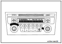
Method of starting
Hardware/software versions and speaker channel check
- Turn the ignition ON.
- Turn the audio system off.
- While pressing the preset 1 button, turn the volume control dial clockwise or counterclockwise 30 clicks or more.
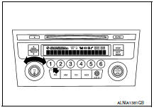
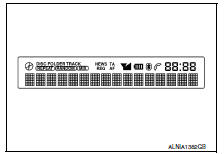
- Initially, all display segments will be illuminated.
- To exit hardware/software versions and speaker channel check, turn the ignition off.
Communication diagnosis
- Turn the ignition on.
- Turn the audio system off.
- While pressing the preset 6 button, turn the volume control dial clockwise or counterclockwise 30 clicks or more.
- Initially, the communication diagnosis mode is displayed.
- To exit communication diagnosis, turn the ignition off.
Self diagnosis mode
Hardware/software versions
- Press the disp button to enter versions display, and the audio head unit software version is displayed.
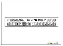
- With each additional press of the disp button, the following information is available:
- Hard v###### (hardware version)
- Eep v###### (eeprom version)
- @@@@ Eq1-4 # (eq pin info)
If an eq error is present, invalid eq is displayed
- Hold the disp button down to return to all display segments screen.
Speaker channel check
- Press the rpt/drm button to enter speaker channel check, and the front left tweeter (front tweeter lh) is displayed.
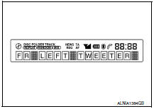
- With each additional press of the RPT/DRM button, the following information is available:
- Fr right tweeter (front tweeter rh)
- Fr right (front door speaker rh)
- RR RIGHT (rear speaker RH)
- Rr left (rear speaker lh)
- Fr left (front door speaker lh)
- Hold the rpt/drm button down to return to all display segments screen.
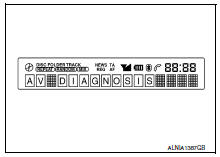
Communication diagnosis
- Press the disp button, and the m-can message transmission error history screen is displayed.
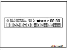
- Press the disp button again, and the tel $$ nn (cmf message reception error history from m-can tel) screen is displayed.
- Press the disp button again, and the trouble del. (Deletion of m-can message communication history) screen is displayed. To retain the m-can message communication history and return to the communication diagnosis mode screen, press the disp button.
- To proceed to the m-can message communication history deletion screen,
press the seek/track
button. The rec del-no? (Selection of m-can message communication history
deletion) screen is displayed.
To cancel m-can message communication history deletion, wait 6 seconds and you will be returned to the trouble del. (Deletion of m-can message communication history) screen. To proceed with m-can message communication history deletion, press the seek/track button again.
- The REC DEL-YES?@ (selection of M-CAN message communication history
deletion) screen is displayed.
To cancel M-CAN message communication history deletion, press the SEEK/TRACK
 button
and you will be returned to the REC DEL-NO? (selection of M-CAN message communication history deletion) screen. To proceed with M-CAN message communication history deletion, wait 6 seconds and the communication history deletion will be executed. After the communication history deletion has been executed, you will be returned to the TROUBLE DEL. (deletion of M-CAN message communication history) screen. To return to the communication diagnosis mode screen, press the DISP button.
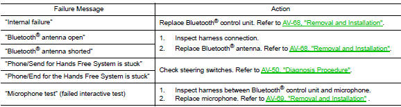
Diagnosis system (bluetoothВ® control unit)
Diagnosis description
The BluetoothВ® control unit has two diagnostic checks. The first diagnostic check is performed automatically every ignition cycle during control unit initialization. The second diagnostic check is performed by the technician using the steering wheel audio control switches prior to trouble diagnosis.
BluetoothВ® control unit initialization checks
- Internal control unit failure
- BluetoothВ® antenna connection open or shorted
- Steering wheel audio control switches [ (
![phone/send), (phone/end)]](images/books/349/84/index550.gif)
phone/send), (phone/end)]
stuck closed - Vehicle speed pulse count
- Microphone connection test (with playback to operator)
- BluetoothВ® inquiry check
Operation procedure
- Turn ignition switch to acc or on.
- Wait for the bluetoothВ® system to complete initialization. This may take up to 20 seconds.
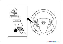
- Press and hold the steering wheel audio control switch

(phone/send) button for at least 5 seconds. The bluetoothВ® system will begin to play a verbal prompt.
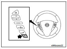
- While the prompt is playing, press and hold the steering wheel
audio control switch
 (phone/end)
button until you hear the “diagnostics mode” prompt. The bluetooth® system will sound a 5-second beep. - While the beep is sounding, press and hold the steering wheel
audio control switch
 (PHONE/END)
button again until you hear prompts. - The BluetoothВ® system has now entered into the diagnostic mode. Results of the diagnostic checks will be verbalized to the technician. Refer to AV-19, "Work Flow".
- After the failure records are reported, an interactive microphone test will be performed. Follow the voice prompt. If the microphone test fails, refer to AV-19, "Work Flow".
Work flow
 Preparation
Special service tools
The actual shape of the tools may differ from those illustrated here.
Commercial service tools
...
 Ecu diagnosis information
Audio unit
Reference value
TERMINAL LAYOUT
PHYSICAL VALUES
1: without BluetoothВ®
2: with BluetoothВ®
BluetoothВ® control unit
Reference value
TERMINAL LAYOUT
PHYSICAL VALUE ...
Other materials:
Can communication circuit
Diagnosis procedure
1.Connector inspection
Turn the ignition switch off.
Disconnect the battery cable from the negative terminal.
Disconnect all the unit connectors on CAN communication system.
Check terminals and connectors for damage, bend and loose connection.
Is the inspection resu ...
Wiring diagram
Remote keyless entry system
Wiring diagram
Power door lock system
Wiring Diagram
Trunk lid opener
Wiring diagram
...
Spark plug
Exploded View
Ignition coil
Spark plug
Rocker cover
Removal and Installation
REMOVAL
Remove engine cover. Refer to EM-24, "Exploded View".
Remove ignition coil. Refer to EM-46, "Exploded View".
Remove spark plug using suitable tool.
(a) : 14 mm (0.55 in ...
