Nissan Sentra Service Manual: System
Tire pressure monitoring system
TIRE PRESSURE MONITORING SYSTEM : System Diagram
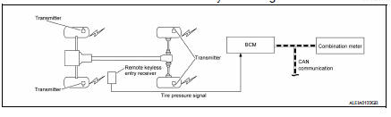
TIRE PRESSURE MONITORING SYSTEM : System Description
- The BCM has pressure judgment and trouble diagnosis functions. When the BCM detects low inflation pressure or another unusual symptom, the low tire pressure warning lamp in the combination meter is illuminated.
- If the tire pressure is less than the specified value, the low tire pressure warning lamp illuminates.
- The TPMS (Tire Pressure Monitoring System) is activated when vehicle speed is 40 km/h (25 MPH) or more.
INPUT/OUTPUT SIGNAL
| Component | Signal Description |
| BCM | Transmits the low tire pressure warning lamp signal via CAN communication to combination meter. |
| Combination meter | Transmits the vehicle speed signal via CAN communication to BCM. |
LOW TIRE PRESSURE WARNING LAMP CONTROL CONDITION
The BCM uses CAN communication to illuminate the low tire pressure warning lamp in the combination meter.
| Condition | Low tire pressure warning lamp |
| Ignition switch OFF | OFF |
| Ignition switch ON (system normal) | Warning light turns on for 1second, then turns off. |
| Low tire pressure | ON |
| Transmitter ID not registered in BCM. | |
| Tire pressure monitoring system malfunction | Warning light blinks 1 minute, then turns on. |
| Tire pressure sensor is in OFF state | Blink (Blinking pattern depends on the positions of nonoperational tire pressure sensors.) |
TIRE PRESSURE MONITORING SYSTEM : Easy Fill Tire Alert Function
NOTE:
When beginning tire inflation, it takes a few seconds for the Easy fill tire alert to function. If there is no response for approximately 15 seconds or more, cancel the Easy fill tire alert function and move the vehicle approximately 1 m (3.2 ft) backward or forward to try again.
- The Easy fill tire alert function operates only when the select lever position is in P-range with the ignition switch ON.
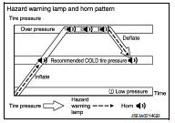
- This function informs the driver with a visual and audible indication that the recommended COLD tire pressure has been reached.
- The hazard warning lamps blink when the recommended COLD tire pressure has been reached. After the recommended COLD tire pressure has been reached, the horn sounds once and the hazard warning lamps stop blinking.
- If the tire pressure value is equal to or greater than 30 kPa (0.31 kg/cm2, 4 psi) more than the recommended COLD tire pressure, the hazard warning lamps flash and horn sounds three times.
- To return the tire to the recommended COLD tire pressure, deflate the tire until the horn sounds once and the hazard warning lamps stop blinking.
 Component parts
Component Parts Location
BCM (view with instrument panel removed)
Remote keyless entry receiver (view
with instrument panel removed)
Transmitter
Combination meter
Component Descript ...
 Diagnosis system (BCM) (with intelligent key system)
Common item
COMMON ITEM : CONSULT Function (BCM - COMMON ITEM)
APPLICATION ITEM
CONSULT performs the following functions via CAN communication with BCM.
Direct Diagnostic Mode
Descriptio ...
Other materials:
Repairing material
Foam Repair
During factory assembly, foam insulators are installed in certain body panels
and locations around the vehicle.
Use the following procedure(s) to replace any factory-installed foam insulators.
URETHANE FOAM APPLICATIONS
Use commercially available Urethane foam for sealant (foam m ...
Compressor
Exploded view
With air conditioning
Compressor
Front
Without air conditioning
A/c idler pulley
A/c idler pulley bracket
Compressor
Compressor : removal and installation
REMOVAL
Discharge the refrigerant. Refer to ha-23, "recycle refrigerant".
Remove the fr ...
Precaution
Precaution for Supplemental Restraint System (SRS) "AIR BAG" and "SEAT
BELT PRE-TENSIONER"
The Supplemental Restraint System such as “AIR BAG” and “SEAT BELT PRE-TENSIONER”,
used along
with a front seat belt, helps to reduce the risk or severity of injur ...
