Nissan Sentra Service Manual: System
Meter system
Meter system : system diagram
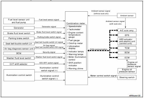
Meter system : system description
COMBINATION METER
The combination meter receives signals from switches, sensors and modules to control the following functions:
- Speedometer/tachometer
- Warning lamps
- Indicator lamps
- Meter illumination control
- Information display
- The combination meter has an integrated buzzer that is activated when it receives a signal from the BCM via CAN communication. Refer to WCS-6, "WARNING CHIME SYSTEM : System Description" for further details.
- The combination meter includes an on-board diagnosis function.
- The combination meter can be diagnosed with CONSULT.
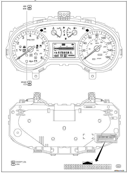
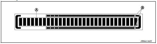
Meter system : arrangement of combination meter
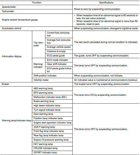
Meter system : fail-safe
The combination meter activates the fail-safe control if CAN communication with each unit is malfunctioning.
Speedometer
Speedometer : system diagram
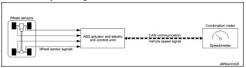
Speedometer : system description
The ABS actuator and electric unit (control unit) receives each wheel speed sensor signal and provides a vehicle speed signal to the combination meter via CAN communication.
Tachometer
Tachometer : system diagram
Tachometer : system description
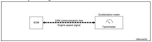
DESCRIPTION
The crank position sensor sends a crankshaft position signal to the ECM. The ECM provides an engine speed signal to the combination meter via CAN communication lines.
The tachometer indicates engine speed in revolutions per minute (rpm).
Engine coolant temperature gauge
Engine coolant temperature gauge : system diagram
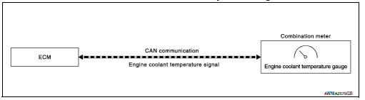
Engine coolant temperature gauge : system description
The engine coolant temperature sensor sends an engine coolant temperature signal to the ECM. The ECM provides an engine coolant temperature signal to the combination meter via CAN communication lines.
The engine coolant temperature gauge indicates the engine coolant temperature.
Fuel gauge
Fuel gauge : system diagram
Fuel gauge : system description
DESCRIPTION
Control Outline
The combination meter reads the fuel level sensor signal from the fuel level sensor unit and indicates the fuel level to the fuel gauge.
Oil pressure warning lamp
OIL PRESSURE WARNING LAMP : System Diagram
SYSTEM DIAGRAM
OIL PRESSURE WARNING LAMP : System Description
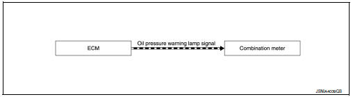
DESCRIPTION
The combination meter turns the oil pressure warning lamp ON when receiving a signal from the ECM via CAN communication.
Meter illumination control
Meter illumination control : system diagram
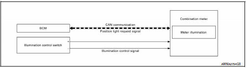
Meter illumination control : system description
METER ILLUMINATION CONTROL
Meter illumination control adjusts the brightness of the combination meter illumination using the illumination control switch.
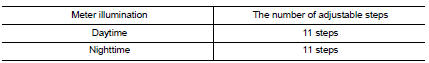
METER ILLUMINATION CONTROL FUNCTION
The operation of the illumination control switch changes brightness of the meter illumination.
Information display
Information display : system diagram
SYSTEM DIAGRAM
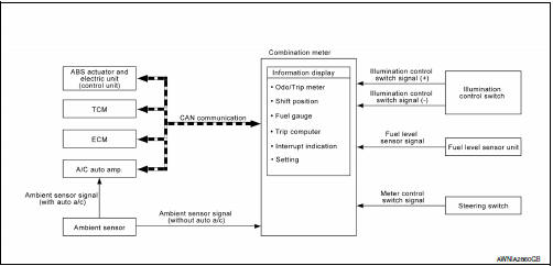
Information display : system description
DESCRIPTION
- The combination meter receives signals necessary for controlling the operation of the information display from each unit, sensor and switch.
- The combination meter incorporates a trip computer that displays the warning/information according to the information received from each unit, sensor and switch.
- The combination meter shows the following functions on the information display.
- Odo/trip meter
- Shift position indicator
- Outside air temperature
- Trip computer
- ECO Pedal Guide
- Warning/Indication messages (check tire pressure and loose fuel cap).
ODO/TRIP METER
The combination meter calculates mileage, based on the following signals and displays the mileage on the information display.
SHIFT POSITION INDICATOR
Displays the position of the shift selector based on signals received from TCM via CAN communication.
OUTSIDE AIR TEMPERATURE INDICATION
Displays the ambient temperature based on signals received from:
- The A/C auto amp. via CAN communication (with auto A/C).
- The ambient sensor (without auto A/C).
LOOSE FUEL CAP
The LOOSE FUEL CAP message will display in the information display when the fuel-filler cap is not tightened correctly. The message will turn off as soon as the ECM detects the fuel-filler cap is properly tightened. The ECM provides a loose fuel cap signal to the combination meter via CAN communication.
LOW TIRE PRESSURE WARNING
This warning appears when the BCM detects low inflation pressure or a system malfunction. The BCM sends a signal to the combination meter via CAN communication to illuminate the low tire pressure warning lamp. In addition, a warning message will be displayed in the vehicle information display.
TRIP COMPUTER
ECO Pedal Guide
The ECO pedal guide displays accelerator pedal angle
 and the guideline of ECO
driving 
according to
information recieved from the ECM via CAN communication.
When the Eco pedal guide bar is in the green range, it indicates that the vehicle is driven within range of economy drive.
If the Eco pedal guide bar is out of green range, it indicates that the accelerator pedal is depressed over the range of economy drive.
Compass
COMPASS : System Description
DESCRIPTION
With the ignition switch in the ON position, and the mode switch ON, the compass display will indicate the direction the vehicle is heading.
Vehicle direction is displayed as follows:
- N: north
- E: east
- S: south
- W: west
ZONE VARIATION SETTING PROCEDURE
The difference between magnetic north and geographical north can sometimes be great enough to cause false compass readings. This difference is known as variance. In order for the compass to operate properly (accurately) in a particular zone, the zone variation must be calibrated using the following procedure.
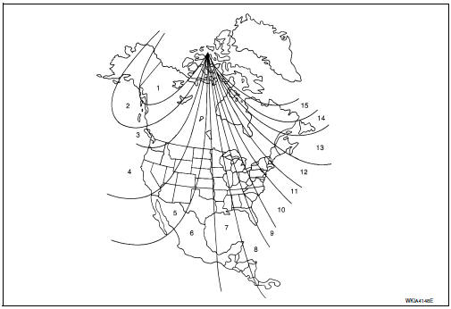
Zone Variation Chart
- Determine your location on the zone map.
- Turn the ignition switch to the ON position.
- Press and hold the mode switch untill the current zone number appears in the display.
- Press the mode switch repeatedly until the desired zone number appears in the display.
Once the desired zone number is displayed, stop pressing the mode switch and the display will show a compass direction after a few seconds.
NOTE:
Use zone number 5 for Hawaii.
CALIBRATION PROCEDURE
The compass display is equipped with an automatic correction function. If the compass display reads “C” or the direction is not shown correctly, perform the correction procedure below.
- Press and hold the mode switch untill the display reads “C”.
- Drive the vehicle slowly in a circle, in an open, safe place. The initial calibration is completed in about 3 turns.
NOTE:
In places where the terrestrial magnetism is extremely disturbed, the initial correction may start automatically.
 Component parts
Meter system
METER SYSTEM : Component Parts Location
ABS actuator and electric unit (control
unit)
Combination meter
CVT shift selector (with CVT)
(O/D OFF switch)
Air bag diag ...
 Diagnosis system (combination meter)
Description
COMBINATION METER SELF-DIAGNOSIS MODE
The information display, speedometer and tachometer can be checked in
self-diagnosis mode.
STARTING COMBINATION METER SELF-DIAGNOSIS MODE
NOTE:
...
Other materials:
Connecting Procedure
NOTE:
The connecting procedure must be performed
when the vehicle is stationary. If the
vehicle starts moving during the procedure,
the procedure will be cancelled.
Press the [ ] button on the
control
panel.
Touch the “Settings” key.
Touch the “Phone & Bluetooth” ke ...
Wiring diagram
Power window system
Wiring Diagram
...
Steering column
Inspection
STEERING COLUMN ASSEMBLY
Check each part of steering column assembly for damage or
other malfunctions. Replace entire steering column
assembly if any parts are damaged.
Measure steering column rotating torque using Tool. Replace
steering column assembly if outside the ...
