Nissan Sentra Owners Manual: Supplemental air bag warning light
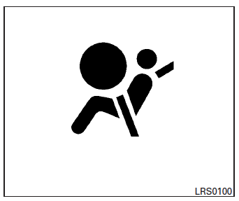
The supplemental air bag warning light,
displaying  in the instrument panel,
monitors
the circuits for the air bag systems, pretensioners
and all related wiring.
When the ignition switch is placed in the ON or START position, the supplemental air bag warning light illuminates for about 7 seconds and then turns off. This means the system is operational.
If any of the following conditions occur, the front air bag, side air bag, curtain air bag and pretensioner systems need servicing:
- The supplemental air bag warning light remains on after approximately 7 seconds.
- The supplemental air bag warning light flashes intermittently.
- The supplemental air bag warning light does not come on at all.
Under these conditions, the front air bag, side air bag, curtain air bag or pretensioner systems may not operate properly. They must be checked and repaired. Take your vehicle to the nearest NISSAN dealer.
| WARNING If the supplemental air bag warning light is on, it could mean that the front air bag, side air bag, curtain air bag and/or pretensioner systems will not operate in an accident. To help avoid injury to yourself or others, have your vehicle checked by a NISSAN dealer as soon as possible. |
Repair and replacement procedure
The front air bags, side air bags, curtain air bags and pretensioners are designed to inflate on a one-time-only basis. As a reminder, unless it is damaged, the supplemental air bag warning light remains illuminated after inflation has occurred.
Repair and replacement of these supplemental air bag systems should be done only by a NISSAN dealer.
When maintenance work is required on the vehicle, the front air bags, side air bags, curtain air bags, pretensioners and related parts should be pointed out to the person performing the maintenance.
The ignition switch should always be placed in the LOCK position when working under the hood or inside the vehicle.
WARNING
|
NOTE:
In the event of a crash involving an airbag deployment (side, front or both), the vehicle’s hazard lamps (turn indicators) will activate.
 Supplemental air bag warning labels
SRS Front Air Bag Warning Labels
Warning labels about the supplemental frontimpact
air bag system are placed in the vehicle as
shown in the illustration. ...

Other materials:
Precaution for work
When removing or disassembling each component, be careful not to damage
or deform it. If a component
may be subject to interference, be sure to protect it with a shop cloth.
When removing (disengaging) components with a screwdriver or similar
tool, be sure to wrap the component
with a ...
System
Body control system
Body control system : system description
OUTLINE
BCM (Body Control Module) controls the various electrical components. It
inputs the information required to
the control from CAN communication and the signal received from each switch
and sensor.
BCM has combination ...
Brake master cylinder
Inspection
Check for brake fluid leakage at the following areas:
Master cylinder mounting face
Reservoir tank mounting face
Brake tube and brake tube connections
Brake hose and brake hose connections
If any brake fluid leakage is found, repair as necessary.
On Board Inspection
LEAK ...
