Nissan Sentra Service Manual: Steering wheel
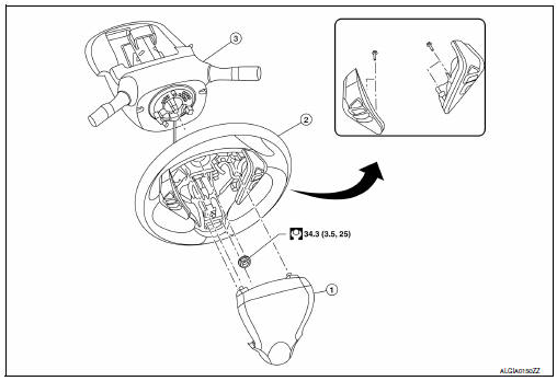
Exploded View
-
Driver air bag module
-
Steering wheel
-
Steering column assembly
Removal and Installation
REMOVAL
NOTE:
When reconnecting spiral cable, fix cable with a tape so that fixing case and rotating part keep aligned. This will omit neutral position alignment procedure during spiral cable installation.
-
Set steering wheel to the straight-ahead position.
-
Remove driver air bag module. Refer to SR-12, "Removal and Installation".
-
Disconnect harness connectors from clipping locations.
-
Remove steering wheel lock nut.
-
Remove steering wheel using suitable tool (A).
NOTE:
Put paint marks on the steering wheel and the column shaft head for supporting accurate positioning during the installation procedure.
Installation is in the reverse order of removal.
-
Check the spiral cable neutral position after replacing or rotating spiral cable. Refer to SR-16, "Removal and Installation".
CAUTION:
-
Do not twist spiral cable excessively after it becomes tight. (Twisting may cause the cable to be torn off.)
-
Do not reuse steering wheel lock nut.

 Steering column
Exploded View
Steering column assembly
Slide plates
lower shaft assembly
Removal and Installation
REMOVAL
CAUTION:
While removing the steering column assembly, do not ...
Other materials:
Precaution for Work
When removing or disassembling each component, be careful not to damage
or deform it. If a component
may be subject to interference, be sure to protect it with a shop cloth.
When removing (disengaging) components with a screwdriver or similar
tool, be sure to wrap the component
with a ...
Rear disc brake
BRAKE PAD
BRAKE PAD : Inspection
PAD WEAR
Check pad thickness from an inspection hole on caliper body. Check
using a scale if necessary.
Wear limit thickness : Refer to BR-55, "Rear Disc
Brake".
DISC ROTOR
DISC ROTOR : Inspection
APPERANCE
Check surface of disc rotor for unev ...
Exhaust gas (carbon monoxide)
WARNINGDo not breathe exhaust gases; they
contain colorless and odorless carbon
monoxide. Carbon monoxide is dangerous.
It can cause unconsciousness or
death.
If you suspect that exhaust fumes are
entering the vehicle, drive with all windows
fully open, and have ...
