Nissan Sentra Service Manual: Steering knuckle
Exploded View
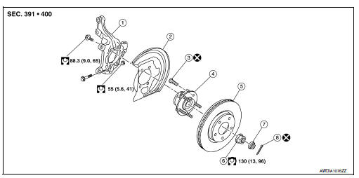
- Steering knuckle
- Splash guard
- Wheel stud
- Wheel hub and bearing
- Disc brake rotor
- Wheel hub lock nut
- Nut retainer
- Cotter pin
Removal and Installation
REMOVAL
- Remove the wheel and tire using power tool. Refer to WT-47, "Exploded View".
- Remove the nut and disconnect the steering outer socket from the steering knuckle. Refer to ST-14, "Removal and Installation".
- Remove the nut and bolt from the lower ball joint. Disconnect the steering knuckle from the transverse link.
- Remove the wheel hub and bearing from the steering knuckle. Refer to FAX-8, "Removal and Installation".
- Remove the splash guard from the steering knuckle.
- Suspend the drive shaft with suitable wire.
- Remove the lower strut nuts and bolts (

). Refer to FSU-8, "Exploded View".
- Remove the steering knuckle.
- Inspect the components. Refer to FSU-15, "Inspection".
INSTALLATION
Installation is in the reverse order of the removal.
CAUTION:
Do not reuse cotter pin.
- Complete the inspection. Refer to FSU-15, "Inspection".
Inspection
INSPECTION AFTER REMOVAL
Check the following items, and replace the part if necessary.
- Check components for deformation, cracks, and other damage.
- Check boots of transverse link and steering outer socket ball joint for breakage, axial end play, and swing torque.
- Transverse link: Refer to FSU-10, "Inspection".
- Steering outer socket: Refer to ST-8, "Inspection".
INSPECTION AFTER INSTALLATION
- Check the wheel sensor harness to be sure the connectors are fully seated.
- Check the wheel alignment. Refer to FSU-6, "Inspection".
 Front stabilizer
Exploded View
Stabilizer bar
Stabilizer clamp
Stabilizer bushing
Stabilizer connecting rod
Front coil spring and strut
Front suspension member
Front
Removal and Installation
RE ...
 Unit removal and installation
Front suspension member
Exploded View
Upper link
Front suspension member
Member stay
Front
Upper link
Front suspension member
Member stay
Front
Removal and Installat ...
Other materials:
Basic inspection
Diagnosis and repair workflow
Work flow
OVERALL SEQUENCE
DETAILED FLOW
1.GET INFORMATION FOR SYMPTOM
Get detailed information from the customer about the symptom (the condition
and the environment when the
incident/malfunction occurred).
>> GO TO 2
2.CONFIRM THE SYMPTOM
Try to ...
Precaution
Precaution for Supplemental Restraint System (SRS) "AIR BAG"
and "SEAT BELT PRE-TENSIONER"
The Supplemental Restraint System such as “AIR BAG” and “SEAT
BELT PRE-TENSIONER”, used along
with a front seat belt, helps to reduce the risk or severity of injur ...
System description
Component parts
Component parts location
Instrument lower finisher
Component description
Eco mode switch
The ECO mode switch is installed to the instrument lower finisher.
When the eco mode indicator lamp on the combination meter is
off and the eco mode switch is pressed, t ...
