Nissan Sentra Service Manual: Steering gear and linkage
Exploded View
REMOVAL
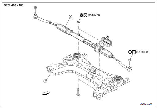
-
Steering gear assembly
-
Front suspension member
 Front
Front
Removal and Installation
REMOVAL
-
Set steering wheel to the straight-ahead position.
-
Remove floor cover (1).
-
Lower shaft assembly (2).
-
Remove the lower shaft assembly bolt and position the lower shaft assembly out of the way. Refer to ST- 12, "Removal and Installation".
CAUTION:
-
Spiral cable may be cut if steering wheel turns while separating steering column assembly and steering gear assembly. Always fix the steering wheel using string to avoid turning.
-
Place a matching mark on both intermediate shaft and steering gear assembly before removing intermediate shaft.
-
Remove wheels and tires using power tool. Refer to WT-47, "Adjustment".
-
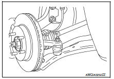
Remove steering outer socket from steering knuckle so as not to damage ball joint boot using Tool.
Tool number : HT72520000 (J-25730-A)
CAUTION:
Temporarily tighten the nut to prevent damage to threads and to prevent the Tool from a sudden drop.
-
Remove front suspension member. Refer to FSU-16, "Removal and Installation".
-
Remove steering gear assembly from front suspension member.
INSTALLATION
Installation is in the reverse order of removal.
CAUTION:
Spiral cable may be cut if steering wheel turns while separating steering column assembly and steering gear assembly. Always fix the steering wheel using string to avoid turning.
-
Perform final tightening of nuts and bolts on each part under unladen conditions with tires on level ground when removing steering gear assembly.
-
Check wheel alignment. Refer to FSU-7, "Adjustment".
-
Rotate steering wheel to check for decentered condition, binding, noise or excessive steering effort.
-
Do not reuse steering outer socket nut and steering gear assembly nut.
-
Perform neutral position steering angle adjustment. Refer to BRC-54, "Work Procedure".
 Steering column
Exploded View
Steering column assembly
Slide plates
lower shaft assembly
Removal and Installation
REMOVAL
CAUTION:
While removing the steering column assembly, do not ...
 Unit disassembly and assembly
Steering gear and linkage
Exploded View
Outer socket
Boot clamp (small diameter)
Boot
Boot clamp (large diameter)
Inner socket
Gear housing assembly
Disassembl ...
Other materials:
Moonroof motor assembly
Exploded view
Headlining
Sun visor
Moonroof motor assembly
Front
Removal and installation
REMOVAL
Close the glass lid.
Remove the map lamp. Refer to INL-52, "Removal and Installation".
Remove the moonroof motor bolts (A).
Front
Disconnect the harness connec ...
Heater operation
This mode is used to direct heated air to the foot
outlets. Some air also flows from the defrost
outlets and the side vent outlets.
Press the button to the OFF
position
for normal heating.
Press the air flow control
button.
Turn the fan control dial to the desired position.
Tur ...
Blower motor
Exploded View
Heating and cooling unit assembly
Blower motor
Front
Removal and Installation
Remove the glove box assembly. Refer to IP-22, "Removal and
Installation".
Disconnect the harness connector from the blower motor.
Remove the blower motor screws.
Remove ...
