Nissan Sentra Service Manual: Removal and installation
ACCELERATOR CONTROL SYSTEM
Exploded View
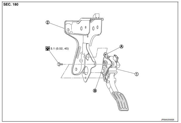
- Accelerator pedal assembly
- Brake pedal bracket
- Locating hook
- Locating pin
Removal and Installation
REMOVAL
- Remove instrument lower panel LH. Refer to IP-21, "Removal and Installation".
- Disconnect the harness connector From the accelerator pedal assembly.
- Loosen bolts and remove accelerator pedal assembly.
CAUTION:
- Do not disassemble accelerator pedal assembly.
- Do not remove accelerator pedal position sensor from accelerator pedal assembly.
- Do not drop or impact the accelerator pedal assembly.
- Do not expose the accelerator pedal assembly to water.
INSTALLATION
Installation is in the reverse order of removal.
- Insert the locating hook and pin into the brake pedal bracket.
CAUTION:
Do not squeeze the locating hook into the brake pedal bracket when inserting the locating pin into the hole on the brake pedal bracket side.
Inspection
INSPECTION AFTER INSTALLATION
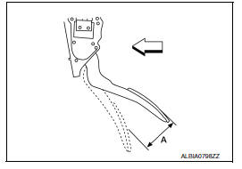
- Check that the accelerator pedal moves smoothly within the specified range.
Accelerator pedal stroke (A) : Refer to ACC-5, "Accelerator Control"
- For the electrical inspection of accelerator pedal position sensor. Refer to EC-138, "Work Procedure".
CAUTION:
- Whenever the harness connector of accelerator pedal position sensor is disconnected, perform “ACCELERATOR PEDAL RELEASED POSITION LEARNING”. Refer to EC-138, "Work Procedure".
- The accelerator pedal should return smoothly to the fully raised position.
 Precaution
Precaution for Supplemental Restraint System (SRS) "AIR BAG" and "SEAT
BELT PRE-TENSIONER"
The Supplemental Restraint System such as “AIR BAG” and “SEAT BELT PRE- ...
 Service data and specifications (SDS)
Accelerator Control
...
Other materials:
Parking brake shoe
Removal and Installation - Drum Brake
If equipped with drum brakes, refer to BR-42, "Removal and
Installation".
Exploded View - Disc Brake
Anti-rattle pin
Back plate
Toggle lever
Parking brake shoe
Brake strut
Return spring
Spring
Adjuster
...
Power outlet
Center Console
Console Box (if so equipped)
The power outlets are for powering electrical
accessories such as cellular telephones. They
are rated at 12 volt, 120W (10A) maximum.
The power outlets are powered only when the
ignition switch is in the ACC or ON position.
CAUTION
The ...
System
EPS system
EPS SYSTEM : System Description
SYSTEM DIAGRAM
DESCRIPTION
EPS control unit performs an arithmetical operation on data,
such
as steering wheel turning force (sensor signal) from the torque
sensor, vehicle speed signal, etc. Then it generates an optimum
assist torque ...
