Nissan Sentra Service Manual: Removal and installation
Audio unit
Exploded view
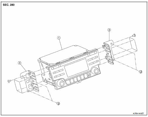
- Audio unit
- Audio unit bracket (LH)
- Audio unit bracket (RH)
Removal and installation
Removal
- Disconnect the negative battery terminal. Refer to pg-50, "removal and installation (battery)".
- Remove cluster lid c lower. Refer to ip-20, "removal and installation - cluster lid c lower".
- Remove the audio unit screws, then pull out the audio unit.
- Disconnect the harness connectors from the audio unit and remove.
Installation
Installation is in the reverse order of removal.
Front tweeter
Removal and Installation
Removal
- Remove the front pillar finisher. Refer to int-24, "front pillar finisher : removal and installation".
- Disconnect the harness connector (b) from the front tweeter speaker.
- Remove the front tweeter speaker screw (A) from the front tweeter speaker (1) and remove.
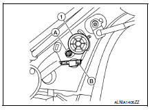
Installation
Installation is in the reverse order of removal.
Front door speaker
Removal and installation
Removal
- Remove the front door finisher. Refer to int-15, "removal and installation".
- Remove the front door speaker screws (b).
- Disconnect the harness connector (a) from the front door speaker (1) and remove.
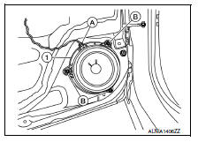
Installation
Installation is in the reverse order of removal.
Rear door speaker
Removal and Installation
Removal
- Remove the rear door finisher. Refer to int-19, "removal and installation".
- Remove the rear door speaker screws (a).
- Disconnect the harness connector (B) from the rear door speaker (1) and remove.
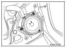
Installation
Installation is in the reverse order of removal.
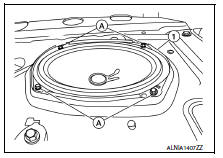
Rear woofer
Removal and Installation
Removal
- Remove the rear parcel shelf finisher. Refer to int-33, "removal and installation".
- Remove the rear woofer screws (a).
- Disconnect the harness connector from the rear woofer (1) and remove.
Installation
Installation is in the reverse order of removal.
Steering switch
Exploded View
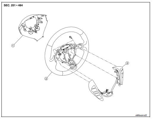
- Steering wheel rear finisher
- Steering wheel
- Steering switches
 Pawl
Pawl
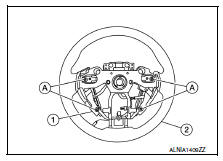
Removal and Installation
Removal
- Remove the steering wheel. Refer to st-10, "removal and installation".
- Release the pawls on the steering wheel rear finisher and remove.
- Remove the steering switches screws (a).
- Remove the steering switches (1) from steering wheel (2).
Installation
Installation is in the reverse order of removal.
Antenna feeder
Location of Antenna
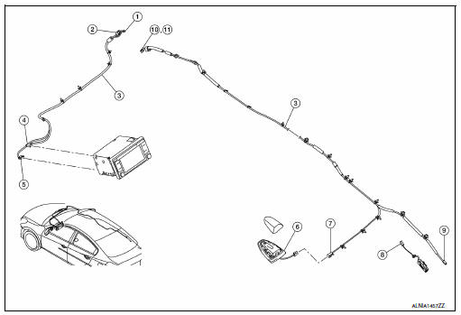
- M112
- M107
- Antenna feeder
- M141
- M140
- Satellite antenna
- M504
- M503
- M502
- M500
- M501
Window Antenna Repair
Element check
- Attach probe circuit tester (ohm setting) to antenna terminal on each side.
- When measuring continuity, wrap tin foil around the top of probe. Then, press the foil against the wire with your finger.
- If an element is broken, no continuity will exist.
- To locate a break, move probe along element. Tester indication will change abruptly when probe passes the broken point.
Repair equipment
- Conductive silver composition (dupont no. 4817 Or equivalent)
- Ruler 30 cm (11.8 In) long
- Drawing pen
- Heat gun
- Alcohol
- Cloth
Repairing procedure
- Wipe broken heat wire and its surrounding area clean with a cloth dampened in alcohol.
- Apply a small amount of conductive silver composition to tip of
drawing pen.
Shake silver composition container before use.
- Place ruler on glass along broken line. Deposit conductive silver composition on break with drawing pen. Slightly overlap existing heat wire on both sides [preferably 5 mm (0.20 in)] of the break.
- After repair has been completed, check repaired wire for continuity.
This check should be conducted 10 minutes after silver composition is deposited.
Do not touch repaired area while test is being conducted.
- Apply a constant stream of hot air directly to the repaired area
for approximately 20 minutes with a heat gun. A minimum distance
of 3 cm (1.2 In) should be kept between repaired area and
hot air outlet.
If a heat gun is not available, let the repaired area dry for 24 hours.
Antenna amp
Removal and installation
Removal
- Remove the rear pillar finisher (rh). Refer to int-29, "rear pillar finisher : removal and installation".
- Disconnect the antenna amp. Harness connector (a) from the rear window glass.
- Disconnect the harness connector (c) from the antenna amp.
(1).
- Remove the antenna amp. screw (B) and the antenna amp. (1).
Installation
Installation is in the reverse order of removal.
Window antenna
Removal and installation
The window antenna is serviced as an assembly with the filament. Refer to def-47, "inspection and repair".
Bose speaker amp
Removal and installation
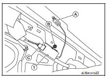
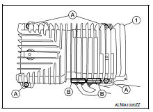
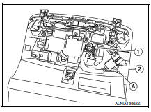
Removal
- Open the trunk lid.
- Remove the Bose speaker amp. screws (A).
- Disconnect the harness connectors (b) from the bose speaker amp. (1) And remove.
Installation
Installation is in the reverse order of removal.
Usb connector
Removal and installation
Removal
- Remove the center console rear finisher cover. Refer to tm-253, "exploded view".
- Release the pawls and remove the usb connector (1) from the center console rear finisher cover.
 Pawl
Pawl
 Front
Front
Installation
Installation is in the reverse order of removal.
Satellite radio antenna
Removal and installation
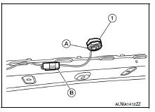
Removal
- Lower the headlining at the rear. Refer to int-38, "exploded view".
- Remove the satellite radio antenna nut (a).
- Disconnect the harness connector (b) from the satellite radio antenna (1) and remove.
Installation
Installation is in the reverse order of removal.
Bluetooth control unit
Removal and Installation
Removal
- Remove the glove box assembly. Refer to IP-22, "Removal and Installation".
- Remove the bluetooth control unit screws (a) and position aside the bluetooth control unit assembly (1).
- Disconnect the bluetooth control unit connectors (c) and release the harness retainer (b) from the bluetooth control unit bracket.
- Release the harness clip (d) from the bluetooth control unit bracket and remove the bluetooth control unit (1).
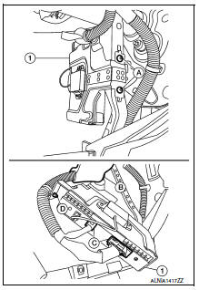
- Remove the bluetooth control unit bracket screws (a), then remove the bluetooth control unit (2) from the bluetooth control unit bracket (1).
Installation
Installation is in the reverse order of removal.
Microphone
Removal and installation
Removal
- Remove the front room/map lamp assembly. Refer to INL-52, "Removal and Installation".
- Disconnect the microphone connector (A) from the front room/ map lamp assembly (2).
- Release the microphone pawls, then remove the microphone (1).
 Pawl
Pawl
Installation
Installation is in the reverse order of removal.
 Symptom diagnosis
Audio system
Symptom table
Related to audio
Related to hands-free phone
Before performing diagnosis, confirm that the cellular phone being used
by the customer is compatible with ...

Other materials:
Daytime light relay circuit
Description
The bcm sends a daytime light request to the ipdm e/r via the can
communication lines. The power flows
through fuse 29 located in fuse block j/b to the daytime light relay coil. When
the ipdm e/r operates the daytime
light relay, power is sent to the daytime lamps.
Diagnosis proc ...
Basic inspection
Diagnosis and repair workflow
Work Flow
Overall sequence
Detailed flow
1.Get information for symptom
Get detailed information from the customer about the symptom (the condition
and the environment when the
incident/malfunction occurred).
>> GO TO 2.
2.Confirm the symptom
Try t ...
P0452 EVAP Control system pressure sensor
DTC Logic
DTC DETECTION LOGIC
DTC No.
CONSULT screen terms
(Trouble diagnosis content)
DTC detecting condition
Possible cause
P0452
EVAP SYS PRES SEN
(Evaporative emission system
pressure sensor/switch low)
An excessively low voltage from the
sensor is se ...
