Nissan Sentra Service Manual: Removal and installation
Bcm (body control module)
Removal and Installation
Note:
Before replacing bcm, perform “read configuration” to save or print current vehicle specification. Refer to bcs-116, "configuration (bcm) : description".
Removal
- Disconnect the negative battery terminal. Refer to pg-52, "removal and installation".
- Remove instrument lower panel lh and instrument side finisher lh. Refer to ip-21, "removal and installation".
- Remove fuse block (j/b) screws (a) and position (bcm) aside.
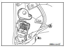
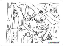
- Remove harness clip (A).
- Remove the screws (A) from the BCM (1).
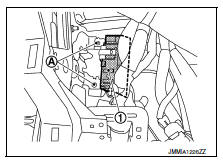
- Disconnect the harness connectors and remove the bcm.
Installation
Installation is in the reverse order of removal.
Caution:
- Perform “configuration (bcm)” when replacing bcm. Refer to bcs-116, "configuration (bcm) : description"
- Be sure to perform the system initialization (nats) when replacing bcm. Refer to bcs-115, "additional service when replacing control unit (bcm) : work procedure".
- When replacing bcm, if new bcm does not come with keyfobs attached, all existing keyfobs must be re-registered.
Combination switch
Exploded view
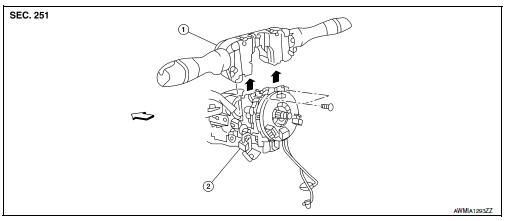
- Combination switch
- Combination switch harness connector
 Front
Front
Note:
Shown with the steering wheel removed for clarity only.
Removal and installation
Removal
Caution:
- Before servicing, turn the ignition switch off, disconnect both battery terminals and wait at least three minutes.
- Do not use air or electric tools when removing or installing the combination switch.
- Disconnect both the negative and positive battery terminals, then wait at least three minutes. Refer to PG- 50, "Removal and Installation (Battery)".
- Remove the steering column covers. Refer to ip-16, "removal and installation".
- Rotate steering wheel clockwise to access first combination switch bolt and remove.
- Rotate steering wheel counter-clockwise to access second combination switch bolt and remove.
- Disconnect the harness connector from the combination switch and remove.
Installation
Installation is in the reverse order of removal.
Caution:
- After the work is completed, make sure no system malfunction is detected by air bag warning lamp.
- In case a malfunction is detected by the air bag warning lamp, reset with the self-diagnosis function and delete the memory with consult.
- If a malfunction is still detected after the above operation,
perform self-diagnosis to repair malfunctions.
Refer to src-41, "additional service when replacing control unit : special repair requirement".
 Symptom diagnosis
Combination switch system symptoms
Symptom Table
Perform the data monitor of consult to check for any malfunctioning
item.
Check the malfunction combinations.
Identify the malfunct ...
 Lan system
...
Other materials:
Work Flow
STEP
DESCRIPTION
STEP 1
Get detailed information about the conditions and the
environment when the incident occurred.
The following are key pieces of information required to make a good
analysis:
WHAT
Vehicle Model, Engine, Transmission/Transaxle and ...
Precaution for Supplemental Restraint System (SRS) "AIR BAG" and "SEAT BELT
PRE-TENSIONER"
The Supplemental Restraint System such as “AIR BAG” and “SEAT BELT PRE-TENSIONER”,
used along
with a front seat belt, helps to reduce the risk or severity of injury to the
driver and front passenger for certain
types of collision. Information necessary to service the system ...
Basic inspection
Diagnosis and repair workflow
Work flow
OVERALL SEQUENCE
DETAILED FLOW
1.INTERVIEW FOR MALFUNCTION
Find out what the customer's concerns are.
>> GO TO 2.
2.SYMPTOM CHECK
Verify the symptom from the customer's information.
>> GO TO 3.
3.BASIC INSPECTION
Check the operat ...
