Nissan Sentra Service Manual: Removal and installation
Horn
Exploded view
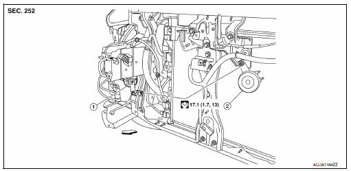
- Horn high
- Horn low
 Front
Front
Note:
Shown with the front fascia removed for clarity.
Removal and installation
Horn low
Removal
- Remove the core support cover. Refer to ext-23, "removal and installation".
- Disconnect the horn low harness connectors.
Note:
The harness connector locations prior to removal.
- Remove the horn nut and the horn low.
Installation
Installation is in the reverse order of removal.
Note:
Install the harness connector in the proper locations.
Horn high
Removal
- Partially remove the rh fender protector. Refer to ext-28, "fender protector : removal and installation - front fender protector".
- Disconnect the horn high harness connectors.
Note:
The harness connector locations prior to removal.
- Remove the horn nut and the horn high.
Installation
Installation is in the reverse order of removal.
Note:
Install the harness connector in the proper locations.
 Wiring diagram
Horn
Wiring diagram
...

Other materials:
Rear disc brake
Exploded View
Sliding pin bolt
Bushing
Cap
Bleeder valve
Cylinder body
Piston seal
Piston
Piston boot
Sliding pin boot
Torque member
Apply rubber grease
Apply brake fluid
Disassembly and Assembly
DISASSEMBLY
Place a wooden block as shown, and blow air from union ...
L terminal circuit (open)
Description
The ą▓ąéčÜLą▓ąéč£ terminal circuit controls the charge warning lamp. The charge warning
lamp turns ON when the ignition
switch is set to ON or START. When the generator is providing sufficient voltage
with the engine running,
the charge warning lamp turns OFF. If the charge warnin ...
System description
Refrigeration system
Component part location
High-pressure service port
High-pressure pipe
Expansion valve
Low-pressure service port
Low-pressure flexible hose
Compressor
Refrigerant pressure sensor
Condenser and liquid tank assembly
High-pressure flexible hose
Refrigera ...
