Nissan Sentra Service Manual: Removal and installation
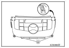
A/C SWITCH ASSEMBLY
Removal and Installation
REMOVAL
- Remove the CVT shift selector finisher (CVT: RE0F11A). Refer to TM-253, "Removal and Installation".
- Remove the MT shift selector finisher (6MT: RS6F94R). Refer to TM-22, "Removal and Installation".
- Remove the A/C switch assembly screws (A).
- Release the A/C switch assembly metal clips using a suitable tool.
 Metal clip
- Disconnect the harness connectors from the A/C switch assembly and remove.
INSTALLATION
Installation is in the reverse order of removal.
A/C AUTO AMP
Exploded View
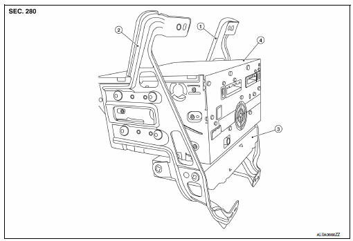
- AV control unit bracket (LH)
- AV control unit bracket (RH)
- A/C auto amp.
- AV control unit
Removal and Installation
REMOVAL
- Remove the AV control unit. Refer to AV-406, "Removal and Installation".
- Remove the AV control unit bracket screws (A).
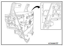
- Remove the A/C auto amp.
INSTALLATION
Installation is in the reverse order of removal.
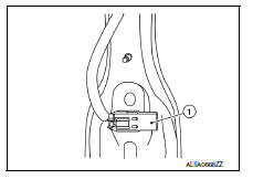
Ambient sensor
Removal and Installation
REMOVAL
- Remove the front under cover. Refer to EXT-30, "FRONT UNDER COVER : Removal and Installation".
- Disconnect the harness connector from the ambient sensor.
- Release the ambient sensor clip, then remove the ambient sensor (1).
INSTALLATION
Installation is in the reverse order of removal.
IN-VEHICLE SENSOR
Removal and Installation
REMOVAL
- Remove the instrument lower panel LH. Refer to IP-21, "Removal and Installation".
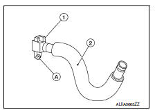
- Disconnect the harness connector from the in-vehicle sensor.
- Disconnect the aspirator hose (2) from the in-vehicle sensor.
- Remove the in-vehicle sensor screw (A) and the in-vehicle sensor (1).
INSTALLATION
Installation is in the reverse order of removal.
SUNLOAD SENSOR
Removal and Installation
REMOVAL
- Release the defroster grille (LH). Refer to VTL-9, "SIDE DEFROSTER GRILLE : Removal and Installation".
- Disconnect the harness connector from the sunload sensor.
- Release the sunload sensor pawls using a suitable tool, then remove the sunload sensor.
INSTALLATION
Installation is in the reverse order of removal.
INTAKE SENSOR
Removal and Installation
The intake sensor is serviced as an assembly with the heating and cooling unit assembly. Refer to HA-43, "HEATING AND COOLING UNIT ASSEMBLY : Removal and Installation".
Refrigerant pressure sensor
Removal and Installation
REMOVAL
- Discharge the refrigerant. Refer to HA-23, "Recycle Refrigerant".
- Remove the core support upper. Refer to HA-39, "Exploded View".
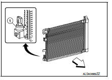
- Disconnect the harness connector from the refrigerant pressure sensor.
- Remove the refrigerant pressure sensor (1).
CAUTION:
Cap or wrap the opening of the refrigerant pressure sensor with suitable material such as vinyl tape to avoid the entry of air.
INSTALLATION
Installation is in the reverse order of removal.
CAUTION:
- Do not reuse O-ring.
- Apply A/C oil to the O-ring of the refrigerant pressure sensor for installation.
- After charging refrigerant, check for leaks. Refer to HA-21, "Leak Test".
Door motor
Exploded View
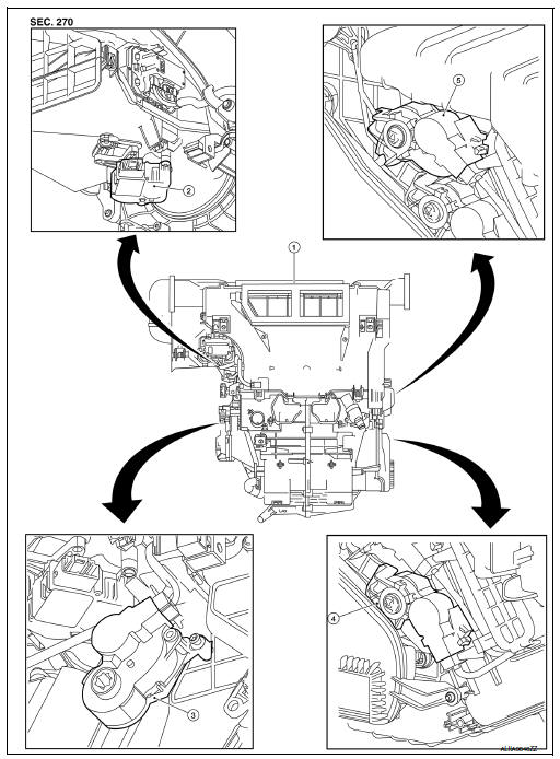
- Heating and cooling unit assembly
- Intake door motor
- Mode door motor
- Air mix door motor lh
- Air mix door motor RH
INTAKE DOOR MOTOR
INTAKE DOOR MOTOR : Removal and Installation
REMOVAL
- Remove the heating and cooling unit assembly. Refer to HA-43, "HEATING AND COOLING UNIT ASSEMBLY : Removal and Installation".
- Disconnect the harness connector from the intake door motor.
- Remove the intake door motor screws and the intake door motor.
Installation
Installation is in the reverse order of removal.
MODE DOOR MOTOR
MODE DOOR MOTOR : Removal and Installation
Removal
- Remove the front floor duct (lh). Refer to vtl-6, "exploded view".
- Disconnect the harness connector from the mode door motor.
- Remove the mode door motor screws and the mode door motor.
INSTALLATION
Installation is in the reverse order of removal.
AIR MIX DOOR MOTOR
AIR MIX DOOR MOTOR : Removal and Installation - Air Mix Door Motor RH
Removal
Remove the glove box. Refer to IP-22, "Removal and Installation".
Disconnect the harness connector from the air mix door motor RH.
Remove the air mix door motor rh screws and the air mix door motor rh.
Installation
Installation is in the reverse order of removal.
AIR MIX DOOR MOTOR : Removal and Installation - Air Mix Door Motor LH
Removal
- Remove the front floor duct (RH). Refer to VTL-6, "Exploded View".
- Disconnect the harness connector from the air mix door motor lh.
- Remove the air mix door motor lh screws and the air mix door motor lh.
Installation
Installation is in the reverse order of removal.
POWER TRANSISTOR
Removal and Installation
REMOVAL
- Remove the instrument lower panel lh. Refer to ip-21, "removal and installation".
- Disconnect the harness connector from the power transistor.
- Release the pawls using a suitable tool and remove the power transistor.
INSTALLATION
Installation is in the reverse order of removal.
 Symptom diagnosis
HEATER AND AIR CONDITIONING SYSTEM
CONTROL SYMPTOMS
Diagnosis Chart By Symptom
Note:
Perform the self-diagnoses with consult before performing the symptom
diagnosis. If dtc is detected, perform
...

Other materials:
System
Body control system
Body control system : system description
OUTLINE
BCM (Body Control Module) controls the various electrical components. It
inputs the information required to
the control from CAN communication and the signal received from each switch
and sensor.
BCM has combination ...
Wiring diagram
Warning chime system
Wiring diagram
...
Tire dressings
NISSAN does not recommend the use of tire
dressings. Tire manufacturers apply a coating to
the tires to help reduce discoloration of the rubber.
If a tire dressing is applied to the tires, it may
react with the coating and form a compound. This
compound may come off the tire while driving and ...
