Nissan Sentra Service Manual: Rear regulator
Exploded View
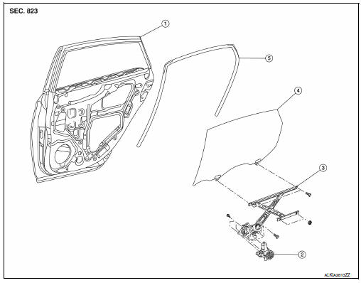
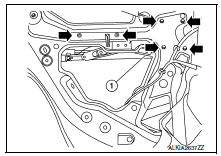
- Rear door panel
- Rear door glass regulator motor
- Rear door glass regulator
- Rear door glass
- Rear door glass rubber run
Removal and Installation
NOTE:
RH rear door panel shown; LH side similar
REMOVAL
- Remove the rear door finisher. Refer to INT-19, "Removal and Installation".
- Remove the vapor barrier.
CAUTION:
Use care to not damage or tear vapor barrier during removal.
- Partially remove the rear door window run rubber.
- Remove bolts (A) and the rear door glass rear run channel (1).
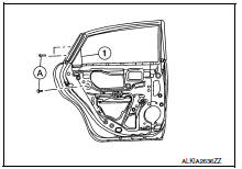
- Temporarily reconnect the rear power window switch to raise/ lower the rear door glass until the rear door regulator to glass bolts (A) can be seen through the access holes.
- Remove the rear door regulator to glass bolts (A).
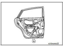
- Raise up the rear door glass and hold with a suction lifter (A).
- Disconnect the harness connector from the rear door glass regulator.
- Remove nuts/bolts (
 ) and
) and
the rear door glass regulator (1).
INSPECTION AFTER REMOVAL
Check the rear door glass regulator for the following items. If a malfunction is detected, replace or grease it.
- Gear wear
- Regulator deformation
- Grease condition for each sliding part
- Apply multi-purpose grease at sliding points.
INSTALLATION
Installation is in the reverse order of removal.
 Rear door glass
Removal and Installation
REMOVAL
NOTE:
LH rear door panel shown; RH similar.
Remove the rear door finisher. Refer to INT-19, "Removal and
Installation".
Remove the vapor barrier. ...
 Rear power window motor
Removal and Installation
REMOVAL
Remove the rear door glass regulator (1). Refer to GW-21,
"Removal and Installation"
Remove the screws and the rear power window motor (2).
I ...
Other materials:
Brake piping
FRONT
FRONT : Exploded View
Brake tube
ABS actuator and electric unit (control
unit)
Connector
Connector bracket
Master cylinder assembly
Brake booster
Lock plate
Brake hose
Copper sealing washer
To front brake hose
To rear brake pipe
Front
FRONT : Hydraulic P ...
Main line between ipdm-e and dlc circuit
Diagnosis procedure
1.Check connector
Turn the ignition switch off.
Disconnect the battery cable from the negative terminal.
Check the following terminals and connectors for damage, bend and loose
connection (connector side
and harness side).
Harness connector e4
Harness connec ...
Precaution for Supplemental Restraint System (SRS) "AIR BAG" and "SEAT BELT
PRE-TENSIONER"
The Supplemental Restraint System such as “AIR BAG” and “SEAT BELT PRE-TENSIONER”,
used along
with a front seat belt, helps to reduce the risk or severity of injury to the
driver and front passenger for certain
types of collision. Information necessary to service the system ...
