Nissan Sentra Service Manual: Precaution for Liquid Gasket
Removal of liquid gasket
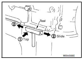
- After removing the bolts and nuts, separate the mating surface and remove the old liquid gasket using tool.
Tool number : kv10111100 (j-37228)
Caution:
Do not damage the mating surfaces.
- Tap the seal cutter to insert it (1).
- In areas where the tool is difficult to use, lightly tap to slide it (2).
Liquid gasket application procedure
- Remove the old liquid gasket adhering to the gasket application surface and the mating surface using suitable tool.
- Remove the liquid gasket completely from the groove of the liquid gasket application surface, bolts, and bolt holes.
- Thoroughly clean the mating surfaces and remove adhering moisture, grease and foreign material.
- Attach the liquid gasket tube to the suitable tool.
Use genuine rtv silicone sealant or equivalent. Refer to gi-21, "recommended chemical products and sealants".
- Apply the liquid gasket without breaks to the specified location with the specified dimensions.
- Attach the liquid gasket tube to the suitable tool.
Use genuine rtv silicone sealant or equivalent. Refer to gi-21, "recommended chemical products and sealants".
- Apply the liquid gasket without breaks to the specified location with the specified dimensions.
- If there is a groove for the liquid gasket application, apply the liquid gasket to the groove.
- Normally apply the liquid gasket on the inside edge of the bolt holes. Also apply to the outside edge of the bolt holes when specified in the procedure.
- Within five minutes of liquid gasket application, install the mating component.
- If the liquid gasket protrudes, wipe it off immediately.
- Do not retighten after the installation.
- Wait 30 minutes or more after installation before refilling the engine with oil or coolant.
Caution:
If there are more specific instructions in the procedures contained in this manual concerning liquid gasket application, observe them.
 Precaution for Supplemental Restraint System (SRS)
"AIR BAG" and "SEAT BELT PRE-TENSIONER"
Precaution for Supplemental Restraint System (SRS)
"AIR BAG" and "SEAT BELT PRE-TENSIONER"
The Supplemental Restraint System such as “AIR BAG” and “SEAT BELT PRE-TENSIONER”,
used along
with a front seat belt, helps to reduce the risk or severity of injury to the
dri ...
 Preparation
Special Service Tool
The actual shape of the tools may differ from those illustrated here.
Commercial Service Tool
...
Other materials:
P2859 Clutch A Pressure
DTC Logic
DTC DETECTION LOGIC
DTC
CONSULT screen terms
(Trouble diagnosis content)
DTC detection condition
Possible causes
P2859
CLUTCH A PRESSURE
(Clutch A Pressure Disengagement
Performance)
The detection conditions continuously for 200
msec or more un ...
Basic inspection
Diagnosis and repair work flow
Work Flow
Overall sequence
Detailed flow
1. Get information for symptom
Get the detailed information from the customer about the symptom (the
condition and the environment when
the incident/malfunction occurred).
>> Go to 2.
2. Check dtc
Check ...
Anti-lock Braking System (ABS)
WARNING
The Anti-lock Braking System (ABS) is a
sophisticated device, but it cannot prevent
accidents resulting from careless
or dangerous driving techniques. It can
help maintain vehicle control during
braking on slippery surfaces. Remember
that stopping distances ...
