Nissan Sentra Service Manual: Power supply and ground circuit
Combination meter
COMBINATION METER : Diagnosis Procedure
Regarding Wiring Diagram information, refer to MWI-28, "Wiring Diagram".
1.Check fuses
Check that the following fuses are not blown.
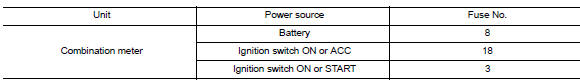
Is the fuse blown? Yes >> replace the blown fuse after repairing the affected circuit.
No >> go to 2.
2.Power supply circuit check
Check voltage between combination meter harness connector m24 terminals 15, 27, 28 and ground
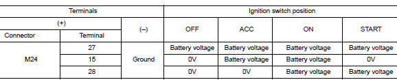
Is the inspection result normal? YES >> GO TO 3.
NO >> Repair or replace harness or connector.
3.Check ground circuit
Check continuity between combination meter harness connector m24 terminals 21, 22, 23 and ground.
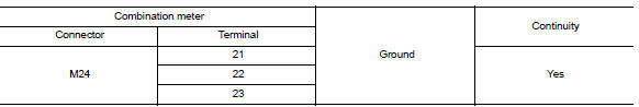
Is the inspection result normal? Yes >> inspection end.
No >> repair or replace harness or connector.
Bcm (body control system) (with intelligent key system)
Bcm (body control system) (with intelligent key system) : diagnosis procedure
Regarding wiring diagram information, refer to bcs-51, "wiring diagram".
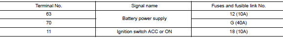
1.Check fuses and fusible link
Check that the following fuses and fusible link are not blown.
Is the fuse blown? Yes >> replace the blown fuse or fusible link after repairing the affected circuit.
No >> go to 2.
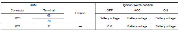
2.Check power supply circuit
- Disconnect bcm connector m85.
- Check voltage between BCM connector M85 and ground.
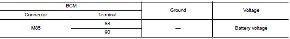
Is the inspection result normal? Yes >> go to 3.
No >> repair harness or connector.
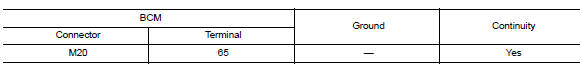
3.Check ground circuit
Check continuity between bcm connector m85 and ground.
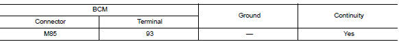
Is the inspection result normal? Yes >> inspection end.
No >> repair harness or connector.
Bcm (body control system) (without intelligent key system)
Bcm (body control system) (without intelligent key system) : diagnosis procedure
Regarding Wiring Diagram information, refer to BCS-111, "Wiring Diagram".
1.Check fuses and fusible link
Check that the following fuses and fusible link are not blown.
Is the fuse blown? Yes >> replace the blown fuse or fusible link after repairing the affected circuit.
No >> go to 2.
2.Check power supply circuit
- Turn ignition switch off.
- Disconnect bcm connectors.
- Check voltage between bcm connector and ground.
Is the inspection result normal? YES >> GO TO 3.
NO >> Repair harness or connector.
3.Check ground circuit
Check continuity between BCM connector and ground.
Is the inspection result normal? Yes >> inspection end.
No >> repair harness or connector.
 B2268 water temp
Description
The engine coolant temperature signal is transmitted from ecm to the
combination meter via can communication.
Dtc logic
Dtc detection logic
Dtc
Consult
Detection condit ...
 Steering switch (meter control switch) signal circuit
Diagnosis Procedure
Regarding wiring diagram information, refer to mwi-28, "wiring diagram".
1.Check combination meter input signal
Turn ignition switch on.
Measure voltage between ...
Other materials:
Removal and installation
A/C SWITCH ASSEMBLY
Removal and Installation
REMOVAL
Remove the CVT shift selector finisher (CVT: RE0F11A). Refer to TM-253,
"Removal and Installation".
Remove the MT shift selector finisher (6MT: RS6F94R). Refer to TM-22,
"Removal and Installation".
Remove the A/ ...
Adjustment of steering angle sensor neutral position
Description
Refer to the table below to determine if adjustment of steering
angle sensor neutral position is required.
×: Required –: Not required
Work Procedure
ADJUSTMENT OF STEERING ANGLE SENSOR NEUTRAL POSITION
CAUTION:
To adjust neutral position of steering angle sensor, ...
Ecu diagnosis information
BCM
Reference value
Note:
The signal tech ii tool (j-50190) can be used to perform the following
functions. Refer to the signal tech ii
user guide for additional information.
Activate and display tpms transmitter ids
Display tire pressure reported by the tpms transmitter
Read TPMS DTCs ...
