Nissan Sentra Service Manual: Power supply and ground circuit
Diagnosis procedure
Regarding wiring diagram information, refer to bcs-51, "wiring diagram".
1.Check fuses and fusible link
Check that the following fuses and fusible link are not blown.
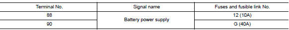
Is the fuse blown? YES >> Replace the blown fuse or fusible link after repairing the affected circuit.
NO >> GO TO 2.
2.Check power supply circuit
- Disconnect bcm connector m85.
- Check voltage between bcm connector m85 and ground.
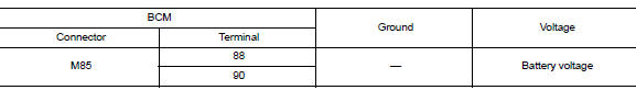
Is the inspection result normal? YES >> GO TO 3.
NO >> Repair harness or connector.
3.Check ground circuit
Check continuity between bcm connector m85 and ground.
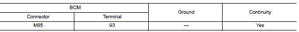
Is the inspection result normal? YES >> Inspection End.
NO >> Repair harness or connector.
Combination meter buzzer
Component function check
1.Check function
- Select intelligent key of bcm using consult.
- Select inside buzzer in active test mode.
- Touch Key, Knob or Take Out to check that it works normally.
Is the inspection result normal? Yes >> Combination meter buzzer is OK.
No >> Refer to DLK-91, "Diagnosis Procedure".
Diagnosis Procedure
1.CHECK METER BUZZER CIRCUIT
Refer to WCS-28, "Component Function Check".
Is the inspection result normal? Yes >> GO TO 2.
No >> Repair or replace harness.
2.CHECK INTERMITTENT INCIDENT
Refer to GI-39, "Intermittent Incident".
>> Inspection End.
 DTC/circuit diagnosis
U1000 CAN COMM CIRCUIT
Description
Refer to lan-7, "can communication system : system description".
Dtc logic
Dtc detection logic
Note:
U1000 can be set if a module harness was disconn ...
 Door lock actuator
Driver side
Driver side : component function check
1.CHECK FUNCTION
Select DOOR LOCK of BCM using CONSULT.
Select DOOR LOCK in ACTIVE TEST mode.
Touch ALL LOCK or ALL UNLK to check that it w ...
Other materials:
Basic inspection
Diagnosis and repair work flow
Work flow
Overall sequence
Detailed flow
1.Get information for symptom
Get the detailed information from the customer about the symptom (the
condition and the environment when
the incident/malfunction occurred) using the “diagnostic work sheet”. ( ...
B0097 Rear side air bag satellite sensor RH
Description
DTC B0097 REAR SATELLITE SENSOR RH
The rear side air bag satellite sensor RH is wired to the air bag diagnosis
sensor unit. The air bag diagnosis
sensor unit will monitor the rear side air bag satellite sensor RH for internal
failures and its circuits for communication
errors.
P ...
Av branch line circuit
Diagnosis Procedure
1.Check connector
Turn the ignition switch off.
Disconnect the battery cable from the negative terminal.
Check the terminals and connectors of the av control unit for damage,
bend and loose connection (unit
side and connector side).
Is the inspection result norma ...
