Nissan Sentra Service Manual: Power generation voltage variable control system operation inspection
Diagnosis Procedure
Regarding wiring diagram information. Refer to chg-9, "wiring diagram".
Caution:
When performing this inspection, always use a charged battery that has completed the battery inspection.
(When the charging rate of the battery is low, the response speed of the voltage change will become slow. This can cause an incorrect inspection.)
1.Check ecm (consult)
Perform ecm self-diagnosis with consult. Refer to ec-66, "consult function".
Self-diagnostic results content
No malfunction detected>> go to 2.
Malfunction detected>> check applicable parts, and repair or replace corresponding parts.
2.Check operation of power generation voltage variable control system
- Connect consult and start the engine.
- The selector lever is in “p” or “n” position and all of the electric loads and a/c, etc. Are turned off.
- Select “alternator duty” in “active test” of “engine”, and then check the value of “battery volt” monitor when duty value of “duty” is set to 40.0 %.
“Battery volt” 2 seconds after setting the duty value of “alternator duty” to 40.0 % : 12 - 13.6 V
- Check the value of “battery volt” monitor when duty value of “duty” is set to 80.0%.
“Battery volt” 20 seconds after setting the duty value of “alternator duty” to 80.0 % : +0.5 V or more against the value of “battery volt” monitor when duty value is 40.0 %
Is the inspection result normal? Yes >> inspection end.
No >> go to 3.
3.Check ipdm e/r (consult)
Perform ipdm e/r self-diagnosis with consult. Refer to pcs-10, "consult function (ipdm e/r)"
(with intelligent key system) or pcs-38, "consult function (ipdm e/r)" (without intelligent key system).
Is the inspection result normal? No malfunction detected>> go to 4.
Malfunction detected>> check applicable parts, and repair or replace corresponding parts.
4.Check harness between generator and ipdm e/r
- Turn ignition switch off.
- Disconnect generator connector and ipdm e/r connector.
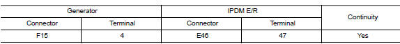
- Check continuity between generator harness connector and ipdm e/r harness connector.
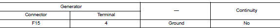
- Check continuity between generator harness connector and ground.
Is the inspection result normal? Yes >> replace ipdm e/r. Refer to pcs-30, "removal and installation".
No >> repair harness or connectors between ipdm e/r and generator.
 Charging system preliminary inspection
Diagnosis Procedure
1.CHECK BATTERY TERMINALS CONNECTION
Check if battery terminals are clean and tight.
Is the inspection result normal?
YES >> GO TO 2.
NO >> Repair battery term ...
 B terminal circuit
Description
“B” terminal circuit supplies power to charge the battery and to operate the
vehicles electrical system.
Diagnosis procedure
Regarding wiring diagram information. Refer to c ...
Other materials:
Glove box assembly
Removal and Installation
REMOVAL
Remove the instrument side finisher RH using a suitable tool.
Remove the glove box assembly upper screws (A).
Remove the glove box assembly lower screws (A).
Disconnect the harness connectors from the trunk switch and glove box
lamp, the ...
Handling precautions for plastics
Precautions for plastics
When repairing and painting a portion of the body adjacent to plastic
parts, consider their characteristics
(influence of heat and solvent) and remove them if necessary or take
suitable measures to protect them.
Plastic parts should be repaired and painted ...
Cleaning exterior
In order to maintain the appearance of your vehicle,
it is important to take proper care of it.
To protect the paint surfaces, please wash your
vehicle as soon as you can:
after a rainfall to prevent possible damage
from acid rain.
after driving on coastal roads.
when contaminants suc ...
