Nissan Sentra Service Manual: Power generation voltage variable control system
System Diagram
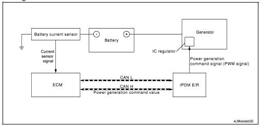
System Description
Power generation variable voltage control system has been adopted. By varying the voltage to the generator, engine load due to power generation of the generator is reduced and fuel consumption is decreased.
NOTE:
When any malfunction is detected in the power generation variable voltage control system, power generation is performed according to the characteristic of the IC regulator in the generator.
 Charging system
System Diagram
System Description
The generator provides DC voltage to operate the vehicle's electrical system
and to keep the battery charged.
The voltage output is controlled by the IC ...
 Wiring diagram
Charging system
Wiring Diagram
...
Other materials:
Seats
WARNING
Do not ride in a moving vehicle when
the seatback is reclined. This can be
dangerous. The shoulder belt will not
be against your body. In an accident,
you could be thrown into it and receive
neck or other serious injuries. You
could also slide under the ...
Help voice commands
The following voice commands can be spoken to
have the system provide instructions and tips for
using the NISSAN Voice Recognition system.
List Commands
What Can I Say?
General Help
Quit
Exit
Symptom/error message
Solution
The system responds “Command Not
Rec ...
P1225 TP Sensor
DTC Logic
DTC DETECTION LOGIC
DTC No.
CONSULT screen terms
(Trouble diagnosis content)
DTC detecting condition
Possible cause
P1225
CTP LEARNING-B1
(Closed throttle position
learning bank 1)
Closed throttle position learning value is excessively
low.
E ...
