Nissan Sentra Service Manual: Periodic maintenance
In-cabin microfilter
Exploded View
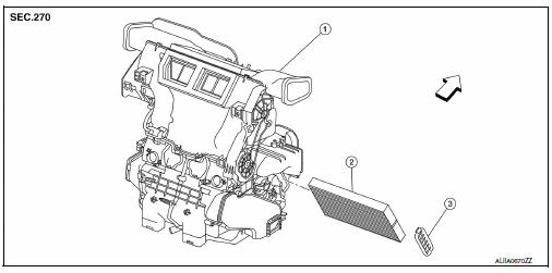
Removal and Installation
REMOVAL
- Remove the in-cabin microfilter cover.
CAUTION:
Before removing the in-cabin micofilter cover, let the vehicle rest for at least 30 minutes.
- Release the filter cover tab (A), then pull the bottom of the in-cabin microfilter cover outwards.
- Pull down the in-cabin microfilter cover to disengage the hook at the top, then remove the in-cabin microfilter cover.
- Remove the in-cabin microfilter.
INSTALLATION
Installation is in the reverse order of removal.
CAUTION:
After installation, check that the in-cabin microfilter cover is securely fastened to the heating and cooling unit assembly.
 Preparation
Special Service Tool
The actual shape of the tools may differ from those illustrated here.
Commercial Service Tool
...
 System description
In-cabin microfilter
Description
FUNCTION
Air inside the passenger compartment is kept clean at either recirculation
or fresh mode by installing an in-cabin microfilter into the heating
and cooli ...
Other materials:
Basic inspection
Diagnosis and repair work flow
Work flow
Detailed flow
1.Obtain information about symptom
Interview the customer to obtain as much information as possible about the
conditions and environment under
which the malfunction occurs.
>> GO TO 2.
2.Check symptom
Check the symptom based ...
During a call
While a call is active, the following options are
available on the screen:
“Handset”
Select this option to switch control of the
phone call over to the handset.
“Mute Mic.”
Select this option to mute the microphone.
Select again to unmute the microphone.
Red phone ( ...
Help voice commands
The following voice commands can be spoken to
have the system provide instructions and tips for
using the NISSAN Voice Recognition system.
List Commands
What Can I Say?
General Help
Quit
Exit
Symptom/error message
Solution
The system responds “Command Not
Rec ...
