Nissan Sentra Owners Manual: Passenger compartment
CAUTION
Never use a fuse of a higher or lower amperage rating than specified on the fuse box cover. This could damage the electrical system or cause a fire.
If any electrical equipment does not operate, check for an open fuse.
NOTE:
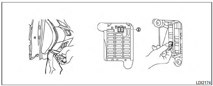
The fuse box is located on the driver’s side of the instrument panel.
- Be sure the ignition switch and the headlight switch are OFF.
- Remove the fuse box cover with a suitable tool. Use a cloth to avoid damaging the trim.
- Locate the fuse that needs to be replaced.
- Remove the fuse with the fuse puller 2 .
- If the fuse is open A , replace it with an equivalent good fuse B .
- Push the fuse box cover to install.
If a new fuse also opens, have the electrical system checked and repaired by a NISSAN dealer.
Extended storage switch
If any electrical equipment does not operate, remove the extended storage switch and check for an open fuse.
NOTE:
The extended storage switch is used for long term vehicle storage. Even if the extended storage switch is broken it is not necessary to replace it. Replace only the open fuse in the switch with a new fuse.
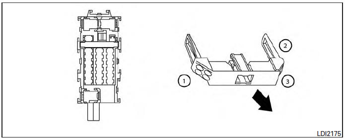
How to replace the extended storage switch:
- To remove the extended storage switch, be sure the ignition switch is in the OFF or LOCK position.
- Be sure the headlight switch is in the OFF position.
- Remove the fuse box cover.
- Pinch the locking tabs 1 and 2 found on each side of the storage switch.
- Pull the storage switch straight out from the fuse box 3 .
 Engine compartment
CAUTION
Never use a fuse of a higher or lower
amperage rating than specified on the
fuse box cover. This could damage the
electrical system or cause a fire.
If any electrical equipment does n ...
 Battery replacement
CAUTION
Be careful not to allow children to swallow
the battery or removed parts. ...
Other materials:
Fuel level sensor signal circuit
Description
The fuel level sensor unit and fuel pump detects the approximate fuel level
in the fuel tank and transmits the
fuel level signal to the combination meter.
Component function check
1.Combination meter input signal
Select meter/m&a on consult.
Using FUEL METER of DATA MONI ...
Bluetooth® Hands-Free Phone System without
Navigation System (Type B) (if so equipped)
WARNING
Use a phone after stopping your vehicle
in a safe location. If you have to use a
phone while driving, exercise extreme
caution at all times so full attention may
be given to vehicle operation.
If you are unable to devote full attention
to vehicle operation ...
Precaution
Precaution for supplemental restraint system (srs) "air bag" and "seat belt pre-tensioner"
The Supplemental Restraint System such as “AIR BAG” and “SEAT BELT PRE-TENSIONER”,
used along
with a front seat belt, helps to reduce the risk or severity of injury ...
