Nissan Sentra Service Manual: Parking brake switch
Component Function Check
1.CHECK PARKING BRAKE SWITCH OPERATION
Check that brake warning lamp in combination meter turns ON/OFF when parking brake is actuated.
Is the inspection result normal? YES >> Inspection End.
NO >> Proceed to diagnosis procedure. Refer to BRC-90, "Diagnosis Procedure".
Diagnosis Procedure
Regarding Wiring Diagram information, refer to BRC-44, "Wiring Diagram".
1.CONNECTOR INSPECTION
-
Turn ignition switch OFF.
-
Disconnect combination meter and parking brake switch connectors.
-
Check connectors and terminals for deformation, disconnection, looseness or damage.
Is the inspection result normal? YES >> GO TO 2.
NO >> Repair or replace as necessary.
2.CHECK PARKING BRAKE SWITCH
Check parking brake switch. Refer to BRC-91, "Component Inspection".
Is the inspection result normal? YES >> GO TO 3.
NO >> Replace parking brake switch. Refer to PB-7, "Exploded View".
3.Check parking brake switch signal
 With CONSULT.
-
Connect combination meter connector and parking brake switch connectors.
-
Turn ignition switch ON.
-
In “DATA MONITOR” select “PARK BRAKE SW” and check parking brake switch signal.
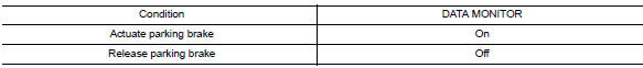
Is the inspection result normal? YES >> Refer to BRC-51, "Work Flow".
NO >> GO TO 4.
4.Check parking brake switch circuit
-
Turn ignition switch OFF.
-
Disconnect combination meter and parking brake switch connectors.
-
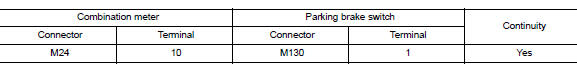
Check continuity between combination meter connector M24 terminal 10 and parking brake switch connector M130 terminal 1.
-
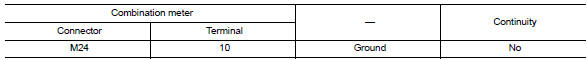
Check continuity between combination meter connector and ground.
Is the inspection result normal? YES >> Replace combination meter. Refer to MWI-77, "Removal and Installation".
NO >> Repair or replace malfunctioning components.
Component Inspection
1.Check parking brake switch
-
Turn ignition switch OFF.
-
Disconnect parking brake switch connector.
-
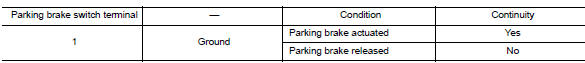
Check continuity between parking brake switch terminal 1 and ground.
Is the inspection result normal? YES >> Inspection End.
NO >> Replace parking brake switch. Refer to PB-7, "Exploded View".
 U1010 Control unit (CAN)
Description
Initial diagnosis of ABS actuator and electric unit (control
unit)
DTC Logic
DTC DETECTION LOGIC
DTC
Items
(CONSULT screen terms)
DTC detection condition
Possible ...
 VDC OFF Switch
Component Function Check
1.CHECK VDC OFF SWITCH OPERATION
Check that VDC OFF indicator lamp in combination meter turns
ON/OFF when VDC OFF switch is operated.
Is the inspection result normal?
...
Other materials:
B0020 Side airbag module LH
Description
DTC B0020 FRONT LH SIDE AIR BAG MODULE
The front LH side air bag module is wired to the air bag diagnosis sensor
unit. The air bag diagnosis sensor
unit will monitor for opens and shorts in detected lines to the front LH side
air bag module.
PART LOCATION
Refer to SRC-5, " ...
P099C Shift solenoid G
DTC Logic
DTC
CONSULT screen terms
(Trouble diagnosis content)
DTC detection condition
Possible causes
P099C
SHIFT SOLENOID G
(Shift Solenoid G Control Circuit
High)
The TCM high clutch & reverse brake solenoid
valve current monitor reading is 200 mA ...
Jump starting
To start your engine with a booster battery, the
instructions and precautions below must be followed.
WARNING
If done incorrectly, jump starting can
lead to a battery explosion, resulting in
severe injury or death. It could also
damage your vehicle.
Explosive hydrogen ga ...
