Nissan Sentra Service Manual: P1651 Starter motor relay
Description
ECM controls ON/OFF state of the starter relay, according to the engine and vehicle condition. ECM transmits a control signal to IPDM E/R by CAN communication.
Under normal conditions, ECM controls and maintains the starter relay in OFF state during following condition:
- Engine is running.
- Selector lever is D position. (CVT models)
- Clutch pedal is fully released. (M/T models)
When detecting a decrease in engine speed due to rapid deceleration or heavy load condition, ECM controls and reactivates the starter relay.
IPDM E/R detects a control state of starter relay and starter control relay and transmits a feedback signal to ECM via CAN communication.
DTC Logic
DTC DETECTION LOGIC
NOTE:
- If DTC P1651 is displayed with DTC U1001, perform the trouble diagnosis for DTC U1001. Refer to EC-169, "DTC Logic".
- If DTC P1651 is displayed with DTC P0607, perform the trouble diagnosis for DTC P0607. Refer to EC-350, "DTC Logic".
| DTC No. | CONSULT screen terms (Trouble diagnosis content) | DTC detecting condition | Possible cause |
| P1651 | STR MTR RELAY (Starter motor relay) | A correlated error is detected for 2 seconds or more between a control signal transmitted from ECM and a feedback signal transmitted from IPDM E/R via CAN communication line. |
|
DTC CONFIRMATION PROCEDURE
1.PRECONDITIONING
If DTC Confirmation Procedure has been previously conducted, always perform the following procedure before conducting the next test.
- Turn ignition switch OFF and wait at least 10 seconds.
- Turn ignition switch ON.
- Turn ignition switch OFF and wait at least 10 seconds.
>> GO TO 2.
2.PERFORM DTC CONFIRMATION PROCEDURE FOR MALFUNCTION
- Turn ignition switch OFF and wait at least 10 seconds.
- Start the engine and let it idle at least 30 seconds.
- Check 1st trip DTC.
Is 1st trip DTC detected? YES >> Proceed to EC-402, "Diagnosis Procedure".
NO >> INSPECTION END
Diagnosis Procedure
1.INSPECTION START
Check the starter motor operation.
Is the starter motor operated? YES >> GO TO 3.
NO >> GO TO 2.
2.CHECK DTC WITH IPDM E/R
Check DTC with IPDM E/R. Refer to PCS-10, "CONSULT Function (IPDM E/R)" (with intelligent key), or PCS- 38, "CONSULT Function (IPDM E/R)" (without intelligent key).
Is the inspection result normal? YES >> GO TO 3.
NO >> Perform trouble diagnosis for DTC indicated. Refer to PCS-20, "DTC Index" (with intelligent key), or PCS-48, "DTC Index" (without intelligent key).
3.CHECK CRANKING REQUEST SIGNAL CIRCUIT-1
- Turn ignition switch OFF.
- Disconnect ECM harness connector.
- Disconnect IPDM E/R harness connector.
- Check the continuity between ECM harness connector and IPDM E/R harness connector.
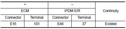
- Also check harness for short to ground to power.
Is the inspection result normal? YES >> GO TO 4.
NO >> Repair or replace error-detected parts.
4.CHECK INTERMITTENT INCIDENT
Check intermittent incident. Refer to GI-39, "Intermittent Incident".
Is the inspection result normal? YES >> Replace IPDM E/R. Refer to PCS-30, "Removal and Installation".
NO >> Repair or replace error-detected parts.
 P1650 Starter motor relay 2
Description
ECM controls ON/OFF state of the starter relay, according to the engine and
vehicle condition. ECM transmits
a control signal to IPDM E/R via BCM by CAN communication.
Under normal ...
 P1652 Starter motor system comm
Description
ECM controls ON/OFF state of the starter relay, according to the engine and
vehicle condition. ECM transmits
a control signal to IPDM E/R via BCM by CAN communication.
Under normal ...
Other materials:
Diagnosis and repair workflow
Work Flow
OVERALL SEQUENCE
*1: Include 1st trip DTC.
*2: Include 1st trip freeze frame data.
DETAILED FLOW
1.GET INFORMATION FOR SYMPTOM
Get the detailed information from the customer about the symptom (the
condition and the environment when
the incident/malfunction occurred) using the ...
P2857 Clutch A Pressure
DTC Logic
DTC DETECTION LOGIC
DTC
CONSULT screen terms
(Trouble diagnosis content)
DTC detection condition
Possible causes
P2857
CLUTCH A PRESSURE
(Clutch A Pressure Engagement
Performance)
The auxiliary gearbox gear ratio is 2.232 or
more for the auxili ...
Changing a flat tire
If you have a flat tire, follow the instructions below:
Stopping the vehicle
Safely move the vehicle off the road and
away from traffic.
Turn on the hazard warning flashers.
Park on a level surface and apply the parking
brake. Shift the manual transmission into R
(Reverse), or the CVT ...
