Nissan Sentra Service Manual: P1586 G Sensor
DTC Logic
DTC DETECTION LOGIC
| DTC | CONSULT screen terms (Trouble diagnosis content) | DTC detection condition | Possible causes |
| P1586 | G Sensor (Gravity Sensor Circuit) | When the following diagnosis conditions are
satisfied and the detection conditions are satisfied
twice in the same DC: Diagnosis conditions
Detection condition
|
|
| When the following diagnosis conditions are satisfied and the detection conditions are satisfied twice in the same DC: Diagnosis conditions
Detection condition
|
NOTE:
DC stands for “DRIVING CYCLE” and indicates a series of driving cycle of “Ignition switch OFF → ON → driving → OFF”.
DTC CONFIRMATION PROCEDURE
CAUTION:
Be careful of the driving speed.
1.PREPARATION BEFORE WORK
If another “DTC CONFIRMATION PROCEDURE” occurs just before, turn ignition switch OFF and wait for at least 10 seconds, then perform the next test.
>> GO TO 2.
2.CHECK DTC DETECTION
 With CONSULT
- With CONSULT
- Drive the vehicle for 10 seconds or more.
- Stop the vehicle.
CAUTION:
Never stop the engine.
- Repeat step 2 through 3.
- Check the DTC.
Is “P1586” detected? YES >> Go to TM-218, "Diagnosis Procedure".
NO >> INSPECTION END
Diagnosis Procedure
1.CHECK G SENSOR SIGNAL
 With CONSULT
- Park the vehicle on a level surface.
- Turn ignition switch ON.
- Select “Data Monitor” in “TRANSMISSION”.
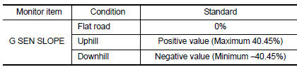
- Select “G SEN SLOPE”.
- Swing the vehicle and check if the value varies between −40.45% and 40.45%.
Is the inspection result normal? YES >> GO TO 2.
NO >> GO TO 3.
2.CALIBRATION OF G SENSOR (PART 1)
 With CONSULT
- Select “Self Diagnostic Results” in “TRANSMISSION”.
- Touch “Erase”.
>> Perform “CALIBRATION OF G SENSOR”. Refer to TM-147, "Work Procedure".
3.CHECK SENSOR POWER SUPPLY
- Turn ignition switch OFF.
- Disconnect G sensor connector.
- Turn ignition switch ON.
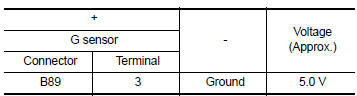
- Check voltage between G sensor harness connector terminal and ground.
Is the inspection result normal? YES >> GO TO 4.
NO >> GO TO 8.
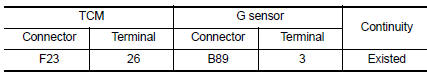
4.CHECK CIRCUIT BETWEEN TCM AND G SENSOR (PART 1)
- Turn ignition switch OFF.
- Disconnect TCM connector.
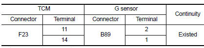
- Check continuity between TCM harness connector terminals and G sensor harness connector terminals.
Is the inspection result normal? YES >> GO TO 5.
NO >> Repair or replace malfunctioning parts.
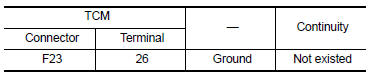
5.CHECK CIRCUIT BETWEEN TCM AND G SENSOR (PART 2)
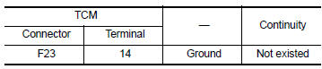
Check continuity between TCM harness connector terminal and ground.
The inspection result normal? Yes >> go to 6.
No >> repair or replace malfunctioning parts.
6.Check g sensor
- Remove g sensor. Refer to tm-265, "removal and installation".
- Connect the all connectors.
- Turn ignition switch on.
- Check voltage between TCM connector terminal and ground.
 : Direction of gravitational
force
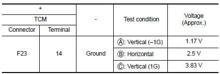
Is the inspection result normal? Yes >> go to 7.
No >> replace g sensor. Refer to tm-265, "removal and installation".
7.Calibration of g sensor (part 2)
 With CONSULT
- Install G sensor. Refer to TM-265, "Removal and Installation".
- Select “Self Diagnostic Results” in “TRANSMISSION”.
- Touch “Erase”.
>> Perform “CALIBRATION OF G SENSOR”. Refer to TM-147, "Work Procedure".
8.CHECK SENSOR POWER SUPPLY CIRCUIT (PART 1)
- Turn ignition switch OFF.
- Disconnect TCM connector.
- Check continuity between TCM harness connector terminal and G sensor harness connector terminal
Is the inspection result normal? YES >> GO TO 9.
NO >> Repair or replace malfunctioning parts.
9.CHECK SENSOR POWER SUPPLY CIRCUIT (PART 2)
Check continuity between TCM harness connector terminal and ground.
Is the inspection result normal? YES >> Check intermittent incident. Refer to GI-39, "Intermittent Incident".
NO >> Repair or replace malfunctioning parts.
 P099C Shift solenoid G
DTC Logic
DTC
CONSULT screen terms
(Trouble diagnosis content)
DTC detection condition
Possible causes
P099C
SHIFT SOLENOID G
(Shift Solenoid G Control Circuit
H ...
 P1588 G Sensor
DTC Logic
DTC DETECTION LOGIC
DTC
CONSULT screen terms
(Trouble diagnosis content)
DTC detection condition
Possible causes
P1588
G Sensor
(Gravity S ...
Other materials:
Unbalance steering wheel turning force and return between right
and left
Description
Unbalance steering wheel turning force and return between right
and left.
Diagnosis Procedure
1.CHECK THE ILLUMINATION OF THE EPS WARNING LAMP
Check the EPS warning lamp while engine is running.
Does the EPS warning lamp turn OFF?
YES >> GO TO 2.
NO >> Refer to S ...
Electrical load signal
Description
The electrical load signal (Headlamp switch signal, rear window defogger
switch signal, etc.) is transferred via
the CAN communication line.
Component Function Check
1.CHECK REAR WINDOW DEFOGGER SWITCH FUNCTION
With CONSULT
Turn ignition switch ON.
Select “DATA MONITORР...
Can communication circuit
Diagnosis procedure
1.Connector inspection
Turn the ignition switch off.
Disconnect the battery cable from the negative terminal.
Disconnect all the unit connectors on CAN communication system.
Check terminals and connectors for damage, bend and loose connection.
Is the inspection resu ...
