Nissan Sentra Service Manual: P1554 Battery current sensor
DTC Logic
DTC DETECTION LOGIC
| DTC No. | CONSULT screen terms (Trouble diagnosis content) | DTC detecting condition | Possible cause |
| P1554 | BAT CURRENT SENSOR (Battery current sensor) | The output voltage of the battery current sensor is lower than the specified value while the battery voltage is high enough. |
|
DTC CONFIRMATION PROCEDURE
1.PERFORM COMPONENT FUNCTION CHECK
Perform component function check. Refer to EC-383, "Component Function Check".
NOTE:
Use component function check to check the overall function of the battery current sensor circuit. During this check, a 1st trip DTC might not be confirmed.
Is the inspection result normal? YES >> INSPECTION END
NO >> Proceed to EC-384, "Diagnosis Procedure".
Component Function Check
1.PRECONDITIONING
TESTING CONDITION:
Before performing the following procedure, confirm that battery voltage is more than 12.8 V at idle.
Before performing the following procedure, confirm that all load switches and A/C switch are turned OFF.
>> GO TO 2.
2.PERFORM COMPONENT FUNCTION CHECK
 With CONSULT
- Start engine and let it idle.
- Select “BAT CUR SEN” in “DATA MONITOR” mode of “ENGINE” using CONSULT.
- Check “BAT CUR SEN” indication for 10 seconds.
“BAT CUR SEN” : above 2,300 mv at least once
 Without
CONSULT
- Start engine and let it idle.
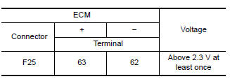
- Check the voltage between ECM harness connectors.
Is the inspection result normal? YES >> INSPECTION END
NO >> Proceed to EC-384, "Diagnosis Procedure".
Diagnosis Procedure
1.CHECK BATTERY CURRENT SENSOR POWER SUPPLY
- Turn ignition switch OFF.
- Disconnect battery current sensor harness connector
- Turn ignition switch ON.
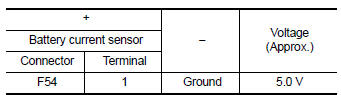
- Check the voltage between battery current sensor harness connector and ground.
Is the inspection result normal? YES >> GO TO 3.
NO >> GO TO 2.
2.CHECK SENSOR POWER SUPPLY 2 CIRCUIT
Check sensor power supply 2 circuit. Refer to EC-444, "Diagnosis Procedure".
Is the inspection result normal? YES >> Perform the trouble diagnosis for power supply circuit.
NO >> Repair or replace error-detected parts.
3.CHECK BATTERY CURRENT SENSOR GROUND CIRCUIT
- Turn ignition switch OFF.
- Disconnect ECM harness connector
- Check the continuity between battery current sensor harness connector and ECM harness connector.
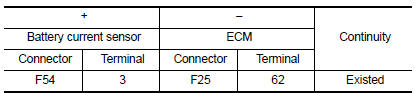
- Also check harness for short to power.
Is the inspection result normal? YES >> GO TO 4.
NO >> Repair or replace error-detected parts.
4.CHECK BATTERY CURRENT SENSOR INPUT SIGNAL CIRCUIT
- Check the continuity between battery current sensor harness connector and ECM harness connector.
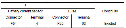
- Also check harness for short to ground and to power.
Is the inspection result normal? YES >> GO TO 5.
NO >> Repair or replace error-detected parts
5.CHECK BATTERY CURRENT SENSOR
Check the battery current sensor. Refer to EC-385, "Component Inspection (Battery Current Sensor)".
Is the inspection result normal? YES >> Check intermittent incident. Refer to GI-39, "Intermittent Incident".
NO >> Replace battery current sensor. Refer to PG-53, "Removal and Installation".
Component Inspection (Battery Current Sensor)
1.CHECK BATTERY CURRENT SENSOR
- Turn ignition switch OFF.
- Reconnect harness connectors disconnected.
- Disconnect battery negative cable.
- Install jumper cable between battery negative terminal and body ground.
- Turn ignition switch ON.
- Check the voltage between ECM harness connector terminals.
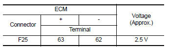
Before measuring the terminal voltage, confirm that the battery is fully charged. Refer to PG-4, "How to Handle Battery".
Is the inspection result normal?
YES >> INSPECTION END
NO >> Replace battery current sensor. Refer to PG-53, "Removal and Installation".
 P1553 Battery current sensor
DTC Logic
DTC DETECTION LOGIC
DTC No.
CONSULT screen terms
(Trouble diagnosis content)
DTC detecting condition
Possible cause
P1553
BAT CURRENT SENSOR
(Battery curr ...
 P1556, P1557 Battery temperature sensor
DTC Logic
DTC DETECTION LOGIC
NOTE:
If DTC P1556 or P1557 is displayed with DTC P0643, first perform the
trouble diagnosis for DTC P0643.
Refer to EC-353, "DTC Logic".
DTC No ...
Other materials:
Road wheel tire assembly
Exploded View
Removal and Installation
REMOVAL
Remove wheel nuts.
Remove wheel and tire.
INSTALLATION
Installation is in the reverse order of removal.
Adjustment
BALANCING WHEELS (ADHESIVE WEIGHT TYPE)
Preparation Before Adjustment
Remove inner and outer balance weights from the ...
P0998 Shift solenoid F
DTC Logic
DTC DETECTION LOGIC
DTC
CONSULT screen terms
(Trouble diagnosis content)
DTC detection condition
Possible causes
P0998
SHIFT SOLENOID F
(Shift Solenoid F Control Circuit
Low)
The TCM low brake solenoid valve current
monitor reading is 200 mA or ...
Timing chain
Exploded View
Timing chain slack guide
Timing chain tensioner
Timing chain
Oil pump drive chain
Crankshaft sprocket
Crankshaft key
Oil pump sprocket
Front cover
O-ring
O-ring
Valve timing control solenoid valve cover
O-ring
Valve timing control solenoid valve
(EXH)
...
