Nissan Sentra Service Manual: P1553 Battery current sensor
DTC Logic
DTC DETECTION LOGIC
| DTC No. | CONSULT screen terms (Trouble diagnosis content) | DTC detecting condition | Possible cause |
| P1553 | BAT CURRENT SENSOR (Battery current sensor) | The signal voltage transmitted from the sensor to ECM is higher than the amount of the maximum power generation. |
|
DTC CONFIRMATION PROCEDURE
1.PRECONDITIONING
If DTC Confirmation Procedure has been previously conducted, always perform the following before conducting the next test.
- Turn ignition switch OFF and wait at least 10 seconds.
- Turn ignition switch ON.
- Turn ignition switch OFF and wait at least 10 seconds.
TESTING CONDITION:
Before performing the following procedure, confirm that battery voltage is more than 8 V at idle.
>> GO TO 2.
2.PERFORM DTC CONFIRMATION PROCEDURE
- Start engine and wait at least 10 seconds.
- Check 1st trip DTC.
Is 1st trip DTC detected? YES >> Proceed to EC-380, "Diagnosis Procedure".
NO >> INSPECTION END
Diagnosis Procedure
1.CHECK BATTERY CURRENT SENSOR POWER SUPPLY
- Turn ignition switch OFF.
- Disconnect battery current sensor harness connector.
- Turn ignition switch ON.
- Check the voltage between battery current sensor harness connector and ground.
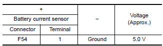
Is the inspection result normal? YES >> GO TO 3.
NO >> GO TO 2.
2.CHECK SENSOR POWER SUPPLY 2 CIRCUIT
Check sensor power supply 2 circuit. Refer to EC-444, "Diagnosis Procedure".
Is the inspection result normal? YES >> Perform the trouble diagnosis for power supply circuit.
NO >> Repair or replace error-detected parts.
3.CHECK BATTERY CURRENT SENSOR GROUND CIRCUIT
- Turn ignition switch OFF.
- Disconnect ECM harness connector.
- Check the continuity between battery current sensor harness connector and ECM harness connector.

- Also check harness for short to power.
Is the inspection result normal? YES >> GO TO 4.
NO >> Repair or replace error-detected parts.
4.CHECK BATTERY CURRENT SENSOR INPUT SIGNAL CIRCUIT
Check the continuity between battery current sensor harness connector and ECM harness connector.

- Also check harness for short to ground and to power.
Is the inspection result normal? YES >> GO TO 5.
NO >> Repair or replace error-detected parts
5.CHECK BATTERY CURRENT SENSOR
Check the battery current sensor. Refer to EC-381, "Component Inspection (Battery Current Sensor)".
Is the inspection result normal? YES >> Check intermittent incident. Refer to GI-39, "Intermittent Incident".
NO >> Replace battery current sensor. Refer to PG-53, "Removal and Installation".
Component Inspection (Battery Current Sensor)
1.CHECK BATTERY CURRENT SENSOR
- Turn ignition switch OFF.
- Reconnect harness connectors disconnected.
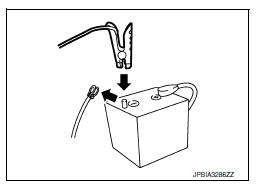
- Disconnect battery negative cable.
- Install jumper cable between battery negative terminal and body ground.
- Turn ignition switch ON.
- Check the voltage between ECM harness connector terminals.
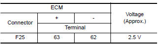
Before measuring the terminal voltage, confirm that the battery is fully charged. Refer to PG-4, "How to Handle Battery".
Is the inspection result normal? YES >> INSPECTION END
NO >> Replace battery current sensor. Refer to PG-53, "Removal and Installation".
 P1551, P1552 Battery current sensor
DTC Logic
DTC DETECTION LOGIC
DTC No.
CONSULT screen terms
(Trouble diagnosis content)
DTC detecting condition
Possible cause
P1551
BAT CURRENT SENSOR
(Battery curr ...
 P1554 Battery current sensor
DTC Logic
DTC DETECTION LOGIC
DTC No.
CONSULT screen terms
(Trouble diagnosis content)
DTC detecting condition
Possible cause
P1554
BAT CURRENT SENSOR
(Battery curr ...
Other materials:
Basic inspection
Diagnosis and repair workflow
Work Flow
OVERALL SEQUENCE
DETAILED FLOW
1. OBTAIN INFORMATION ABOUT SYMPTOM
Interview the customer to obtain as much information as possible about the
conditions and environment under
which the malfunction occurred.
>> GO TO 2.
2. CONFIRM THE SYMPTO ...
B2268 water temp
Description
The engine coolant temperature signal is transmitted from ecm to the
combination meter via can communication.
Dtc logic
Dtc detection logic
Dtc
Consult
Detection condition
Probable malfunction location
B2268
Water temp meter
[b2268]
Ecm continuous ...
U1010 Control unit (CAN)
Description
Air bag diagnosis sensor performs self-tests on key ON. If CAN communication
failure within control unit is
detected, DTC is set.
DTC Logic
DTC DETECTION LOGIC
CONSULT name
DTC
DTC detecting condition
Repair order
CAN CONTROL UNIT FAILURE
U1010
CAN ...
