Nissan Sentra Service Manual: P1550 Battery current sensor
DTC Logic
DTC DETECTION LOGIC
| DTC No. | CONSULT screen terms (Trouble diagnosis content) | DTC detecting condition | Possible cause |
| P1550 | BAT CURRENT SENSOR (Battery current sensor) | The output voltage of the battery current sensor remains within the specified range while engine is running. |
|
DTC CONFIRMATION PROCEDURE
1.PRECONDITIONING
If DTC Confirmation Procedure has been previously conducted, always perform the following before conducting the next test.
- Turn ignition switch OFF and wait at least 10 seconds.
- Turn ignition switch ON
- Turn ignition switch OFF and wait at least 10 seconds.
TESTING CONDITION:
Before performing the following procedure, confirm that battery voltage is more than 8 V at idle.
>> GO TO 2.
2.PERFORM DTC CONFIRMATION PROCEDURE
- Start engine and wait at least 10 seconds.
- Check 1st trip DTC.
Is 1st trip DTC detected? YES >> Proceed to EC-374, "Diagnosis Procedure".
NO >> INSPECTION END
Diagnosis Procedure
1.CHECK BATTERY CURRENT SENSOR POWER SUPPLY
- Turn ignition switch OFF.
- Disconnect battery current sensor harness connector.
- Turn ignition switch ON.
- Check the voltage between battery current sensor harness connector and ground.
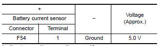
Is the inspection result normal? YES >> GO TO 3.
NO >> GO TO 2.
2.CHECK SENSOR POWER SUPPLY 2 CIRCUIT
Check sensor power supply 2 circuit. Refer to EC-444, "Diagnosis Procedure".
Is the inspection result normal? YES >> Perform the trouble diagnosis for power supply circuit.
NO >> Repair or replace error-detected parts.
3.CHECK BATTERY CURRENT SENSOR GROUND CIRCUIT
- Turn ignition switch OFF.
- Disconnect ECM harness connector.
- Check the continuity between battery current sensor harness connector and ECM harness connector.
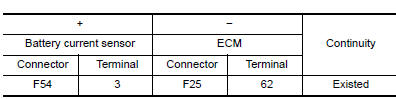
- Also check harness for short to power.
Is the inspection result normal? YES >> GO TO 4.
NO >> Repair or replace error-detected parts.
4.CHECK BATTERY CURRENT SENSOR INPUT SIGNAL CIRCUIT
- Check the continuity between battery current sensor harness connector and ECM harness connector.
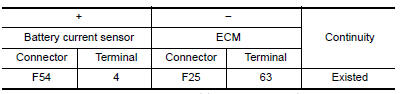
- Also check harness for short to ground and to power.
Is the inspection result normal? YES >> GO TO 5.
NO >> Repair or replace error-detected parts
5.CHECK BATTERY CURRENT SENSOR
Check the battery current sensor. Refer to EC-375, "Component Inspection (Battery Current Sensor)".
Is the inspection result normal? YES >> Check intermittent incident. Refer to GI-39, "Intermittent Incident".
NO >> Replace battery current sensor. Refer to PG-53, "Removal and Installation".
Component Inspection (Battery Current Sensor)
1.CHECK BATTERY CURRENT SENSOR
- Turn ignition switch OFF.
- Reconnect harness connectors disconnected.
- Disconnect battery negative cable.
- Install jumper cable between battery negative terminal and body ground.
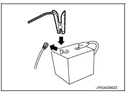
- Turn ignition switch ON.
- Check the voltage between ECM harness connector terminals.
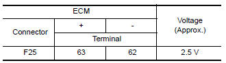
Before measuring the terminal voltage, confirm that the battery is fully charged. Refer to PG-4, "How to Handle Battery".
Is the inspection result normal? YES >> INSPECTION END
NO >> Replace battery current sensor. Refer to PG-53, "Removal and Installation".
 P1226 TP Sensor
DTC Logic
DTC DETECTION LOGIC
DTC No.
CONSULT screen terms
(Trouble diagnosis content)
DTC detecting condition
Possible cause
P1226
CTP LEARNING-B1
(CTP LEARNING-B1 ...
 P1551, P1552 Battery current sensor
DTC Logic
DTC DETECTION LOGIC
DTC No.
CONSULT screen terms
(Trouble diagnosis content)
DTC detecting condition
Possible cause
P1551
BAT CURRENT SENSOR
(Battery curr ...
Other materials:
Rear combination lamp
Exploded View
Rear combination lamp
Rear turn signal lamp bulb
Rear turn signal lamp socket
LED lamp harness connector
Rear combination lamp harness
connector
Back-up lamp bulb socket
Back-up lamp bulb
Disassembly and Assembly
DISASSEMBLY
WARNING:
Do not touch bulb whil ...
Precaution for Supplemental Restraint System (SRS) "AIR BAG" and "SEAT
BELT PRE-TENSIONER"
The Supplemental Restraint System such as “AIR BAG” and “SEAT BELT PRE-TENSIONER”,
used along
with a front seat belt, helps to reduce the risk or severity of injury to the
driver and front passenger for certain
types of collision. Information necessary to service the system ...
Battery terminal with fusible link
Exploded view
Battery terminal with fusible link
Harness connector
Removal and installation
Removal
Loosen the battery terminal nuts and disconnect both battery negative and
positive terminals. Refer to
pg-50, "exploded view".
Caution:
To prevent damage to the parts, di ...
