Nissan Sentra Service Manual: P099C Shift solenoid G
DTC Logic
| DTC | CONSULT screen terms (Trouble diagnosis content) | DTC detection condition | Possible causes |
| P099C | SHIFT SOLENOID G (Shift Solenoid G Control Circuit High) | The TCM high clutch & reverse brake solenoid
valve current monitor reading is 200 mA or
less continuously for 200 msec or more under
the following diagnosis conditions: Diagnosis conditions
|
|
DTC CONFIRMATION PROCEDURE
1.PREPARATION BEFORE WORK
If another –≤–В—ЪDTC CONFIRMATION PROCEDURE–≤–В—Ь occurs just before, turn ignition switch OFF and wait for at least 10 seconds, then perform the next test.
>> GO TO 2.
2.CHECK DTC DETECTION
- Start the engine and wait for 5 seconds or more
- Check the first trip DTC.
Is –≤–В—ЪP099C–≤–В—Ь detected? YES >> Go to TM-216, "Diagnosis Procedure".
NO >> INSPECTION END
Diagnosis Procedure
1.CHECK CIRCUIT BETWEEN TCM AND CVT UNIT
- Turn ignition switch OFF.
- Disconnect TCM connector and CVT unit connector.
- Check continuity between TCM harness connector terminal and CVT unit harness connector terminal.
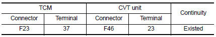
Is the inspection result normal? YES >> GO TO 2.
NO >> Repair or replace malfunctioning parts.
2.CHECK HIGH CLUTCH & REVERSE BRAKE SOLENOID VALVE
Check high clutch & reverse brake solenoid valve. Refer to TM-216, "Component Inspection".
Is the inspection result normal? YES >> Check intermittent incident. Refer to GI-39, "Intermittent Incident".
NO >> Repair or replace malfunctioning parts.
Component Inspection
1.CHECK HIGH CLUTCH & REVERSE BRAKE SOLENOID VALVE
Check resistance between CVT unit connector terminal and ground.
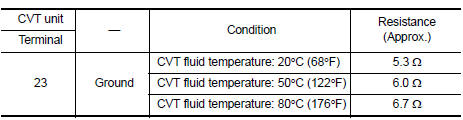
Is the inspection result normal? YES >> INSPECTION END
NO >> There is a malfunction of high & reverse brake solenoid valve. Replace transaxle assembly. Refer to TM-283, "Removal and Installation".
 P099B Shift solenoid G
DTC Logic
DTC DETECTION LOGIC
DTC
CONSULT screen terms
(Trouble diagnosis content)
DTC detection condition
Possible causes
P099B
SHIFT SOLENOID G
(Shift Solenoid G ...
 P1586 G Sensor
DTC Logic
DTC DETECTION LOGIC
DTC
CONSULT screen terms
(Trouble diagnosis content)
DTC detection condition
Possible causes
P1586
G Sensor
(Gravity Sensor Circuit)
...
Other materials:
U1010 Control unit (CAN)
Description
Air bag diagnosis sensor performs self-tests on key ON. If CAN communication
failure within control unit is
detected, DTC is set.
DTC Logic
DTC DETECTION LOGIC
CONSULT name
DTC
DTC detecting condition
Repair order
CAN CONTROL UNIT FAILURE
U1010
CAN ...
Bluetooth¬Ѓ settings
To access and adjust the settings for the
Bluetooth¬Ѓ Hands-Free Phone System:
Press the SETTING button.
Use the TUNE/SCROLL knob to select
вАЬBluetoothвАЭ and then press the ENTER button:
Bluetooth
Select вАЬOnвАЭ or вАЬOffвАЭ to turn the vehicleвАЩs
Bluetooth¬Ѓ system on or ...
Power outlet
Center Console
Console Box (if so equipped)
The power outlets are for powering electrical
accessories such as cellular telephones. They
are rated at 12 volt, 120W (10A) maximum.
The power outlets are powered only when the
ignition switch is in the ACC or ON position.
CAUTION
The ...
