Nissan Sentra Service Manual: P0966 Pressure control solenoid B
DTC Logic
DTC DETECTION LOGIC
| DTC | CONSULT screen terms (Trouble diagnosis content) | DTC detection condition | Possible causes |
| P0966 | PC SOLENOID B (Pressure Control Solenoid B Control Circuit Low) | The primary pressure solenoid valve current is
200 mA or less continuously for 480 msec or
more under the following diagnosis conditions: Diagnosis conditions
|
|
DTC CONFIRMATION PROCEDURE
1.PREPARATION BEFORE WORK
If another “DTC CONFIRMATION PROCEDURE” occurs just before, turn ignition switch OFF and wait for at least 10 seconds, then perform the next test.
>> GO TO 2.
2.CHECK DTC DETECTION
- Start the engine and wait for 5 seconds or more.
- Check the first trip DTC.
Is “P0966” detected? YES >> Go to TM-206, "Diagnosis Procedure".
NO >> INSPECTION END
Diagnosis Procedure
1.CHECK CIRCUIT BETWEEN TCM AND CVT UNIT
- Turn ignition switch OFF.
- Disconnect TCM connector and CVT unit connector.
- Check continuity between TCM harness connector terminal and ground.
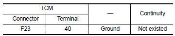 Is the inspection
result normal?
YES >> GO TO 2.
NO >> Repair or replace malfunctioning parts.
2.CHECK PRIMARY PRESSURE SOLENOID VALVE
Check primary pressure solenoid valve. Refer to TM-206, "Component Inspection".
Is the inspection result normal? YES >> Check intermittent incident. Refer to GI-39, "Intermittent Incident".
NO >> Repair or replace malfunctioning parts.
Component Inspection
1.CHECK PRIMARY PRESSURE SOLENOID VALVE
Check resistance between CVT unit connector terminal and ground.
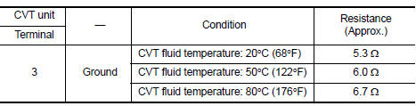 Is the inspection
result normal?
YES >> INSPECTION END
NO >> There is a malfunction of primary pressure solenoid valve. Replace transaxle assembly. Refer to TM-283, "Removal and Installation".
 P0965 Pressure control solenoid B
DTC Logic
DTC DETECTION LOGIC
DTC
CONSULT screen terms
(Trouble diagnosis content)
DTC detection condition
Possible causes
P0965
PC SOLENOID B
(Pressure control sol ...
 P0967 Pressure control solenoid B
DTC Logic
DTC DETECTION LOGIC
DTC
CONSULT screen terms
(Trouble diagnosis content)
DTC detection condition
Possible causes
P0967
PC SOLENOID B
(Pressure Control So ...
Other materials:
Periodic maintenance
FUEL SYSTEM
Inspection
Inspect fuel lines, fuel filler cap, and fuel tank for improper attachment,
leakage, cracks, damage, loose connections, chafing or deterioration.
Engine
Fuel line
Fuel tank
If necessary, repair or replace damaged parts.
Quick Connector
CAUTION:
After c ...
Evaporative emission system
EVAPORATIVE EMISSION SYSTEM : System Description
SYSTEM DIAGRAM
INPUT/OUTPUT SIGNAL CHART
Sensor
Input signal to ECM
ECM function
Actuator
Crankshaft position sensor (POS)
Engine speed*
EVAP canister
purge flow control
EVAP canister purge volume
control ...
Dlc branch line circuit
Diagnosis procedure
1.Check connector
Turn the ignition switch off.
Disconnect the battery cable from the negative terminal
Check the terminals and connectors of the data link connector for damage,
bend and loose connection
(connector side and harness side).
Is the inspection result ...
