Nissan Sentra Service Manual: P0963 Pressure control solenoid A
DTC Logic
DTC DETECTION LOGIC
| DTC | CONSULT screen terms (Trouble diagnosis content) | DTC detection condition | Possible causes |
| P0963 | PC SOLENOID A (Pressure Control Solenoid A Control Circuit High) | The line pressure solenoid valve current is 200
mA or less continuously for 200 msec or more
under the following diagnosis conditions: Diagnosis conditions
|
|
DTC CONFIRMATION PROCEDURE
1.PREPARATION BEFORE WORK
If another “DTC CONFIRMATION PROCEDURE” occurs just before, turn ignition switch OFF and wait for at least 10 seconds, then perform the next test.
>> GO TO 2.
2.CHECK DTC DETECTION
- Start the engine and wait for 5 seconds or more.
- Check the first trip DTC.
Is “P0963” detected? YES >> Go to TM-203, "Diagnosis Procedure".
NO >> INSPECTION END
Diagnosis Procedure
1.CHECK CIRCUIT BETWEEN TCM AND CVT UNIT
- Turn ignition switch OFF.
- Disconnect TCM connector and CVT unit connector.
- Check continuity between TCM harness connector terminal and CVT unit harness connector terminal.
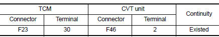
Is the inspection result normal? YES >> GO TO 2.
NO >> Repair or replace malfunctioning parts.
2.CHECK LINE PRESSURE SOLENOID VALVE
Check line pressure solenoid valve. Refer to TM-203, "Component Inspection".
Is the inspection result normal? YES >> Check intermittent incident. Refer to GI-39, "Intermittent Incident".
NO >> Repair or replace malfunctioning parts.
Component Inspection
1.CHECK LINE PRESSURE SOLENOID VALVE
Check resistance between CVT unit connector terminal and ground.
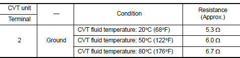 Is the inspection
result normal?
YES >> INSPECTION END
NO >> There is a malfunction of line pressure solenoid valve. Replace transaxle assembly. Refer to TM- 283, "Removal and Installation".
 P0962 Pressure control solenoid A
DTC Logic
DTC DETECTION LOGIC
DTC
CONSULT screen terms
(Trouble diagnosis content)
DTC detection condition
Possible causes
P0962
PRESSURE CONTROL SOLENOID
A
(Pre ...
 P0965 Pressure control solenoid B
DTC Logic
DTC DETECTION LOGIC
DTC
CONSULT screen terms
(Trouble diagnosis content)
DTC detection condition
Possible causes
P0965
PC SOLENOID B
(Pressure control sol ...
Other materials:
Front passenger side power window does not operate
When both power window main switch and front power window switch are
operated
WHEN BOTH POWER WINDOW MAIN SWITCH AND FRONT POWER WINDOW SWITCH ARE OPERATED
: Diagnosis Procedure
1.CHECK FRONT POWER WINDOW SWITCH (PASSENGER SIDE)
Check front power window switch (passenger side).
Refer to PW ...
B1430, B1432 Seat belt pre-tensioner LH
Description
DTC B1430, B1432 SEAT BELT PRE-TENSIONER LH
The seat belt pre-tensioner LH is wired to the air bag diagnosis sensor unit.
The air bag diagnosis sensor unit
will monitor for opens and shorts in detected lines to the seat belt pre-tensioner
LH.
PART LOCATION
Refer to SRC-5, " ...
Can communication circuit
Diagnosis procedure
1.Connector inspection
Turn the ignition switch OFF.
Disconnect the battery cable from the negative terminal.
Disconnect all the unit connectors on can communication system.
Check terminals and connectors for damage, bend and loose connection.
Is the inspection resu ...
