Nissan Sentra Service Manual: P0713 Transmission fluid temperature sensor A
DTC Logic
DTC DETECTION LOGIC
| DTC | CONSULT screen terms (Trouble diagnosis content) | DTC detection condition | Possible causes |
| P0713 | FLUID TEMP SENSOR A (Transmission Fluid Temperature Sensor A Circuit High) | The CVT fluid temperature identified by the
TCM is −40В°C (−40В°F) or less continuously for
5 seconds or more under the following diagnosis
conditions: Diagnosis conditions
|
|
DTC CONFIRMATION PROCEDURE
1.PREPARATION BEFORE WORK
If another “DTC CONFIRMATION PROCEDURE” occurs just before, turn ignition switch OFF and wait for at least 10 seconds, then perform the next test.
>> GO TO 2.
2.PERFORM DTC CONFIRMATION PROCEDURE
- Start the engine.
- Maintain the following condition for 10 seconds or more.
Vehicle speed : 20 km/h (12 MPH) or more
- Stop the vehicle.
- Check the first trip DTC.
Is “P0713” detected? YES >> Go to TM-176, "Diagnosis Procedure".
NO >> INSPECTION END
Diagnosis Procedure
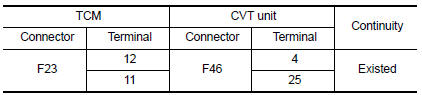
1.CHECK CIRCUIT BETWEEN TCM AND CVT UNIT (PART 1)
- Turn ignition switch OFF.
- Disconnect TCM connector and CVT unit connector.
- Check continuity between TCM harness connector terminals and CVT unit harness connector terminals.
Is the inspection result normal? YES >> GO TO 2.
NO >> Repair or replace malfunctioning part.
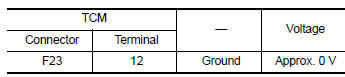
2.CHECK CIRCUIT BETWEEN TCM AND CVT UNIT (PART 2)
- Turn ignition switch ON.
- Check voltage between TCM harness connector terminal and ground.
Is the inspection result normal? YES >> GO TO 3.
NO >> Repair or replace malfunctioning part.
3.CHECK CVT FLUID TEMPERATURE SENSOR
Check CVT fluid temperature sensor. Refer to TM-177, "Component Inspection".
Is the inspection result normal? YES >> Check intermittent incident. Refer to GI-39, "Intermittent Incident".
NO >> Repair or replace malfunctioning parts.
Component Inspection
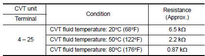
1.CHECK CVT FLUID TEMPERATURE SENSOR
Check resistance between CVT unit connector terminals.
Is the inspection result normal? YES >> INSPECTION END
NO >> There is a malfunction of CVT fluid temperature sensor. Replace transaxle assembly. Refer to TM-283, "Removal and Installation".
 P0712 Transmission fluid temperature sensor A
DTC Logic
DTC DETECTION LOGIC
DTC
CONSULT screen terms
(Trouble diagnosis content)
DTC detection condition
Possible causes
P0712
FLUID TEMP SENSOR A
(Transmission F ...
 P0715 Input speed sensor A
DTC Logic
DTC DETECTION LOGIC
DTC
CONSULT screen terms
(Trouble diagnosis content)
DTC detection condition
Possible causes
P0715
INPUT SPEED SENSOR A
...
Other materials:
Precaution
Precaution for Supplemental Restraint System (SRS) "AIR BAG" and "SEAT
BELT PRE-TENSIONER"
The Supplemental Restraint System such as “AIR BAG” and “SEAT BELT PRE-TENSIONER”,
used along
with a front seat belt, helps to reduce the risk or severity of injur ...
Dtc/circuit diagnosis
U1000 can comm circuit
DTC Logic
Dtc detection logic
Consult display
Dtc detection condition
Possible cause
Can comm circuit
[u1000]
Av control unit is not transmitting or receiving
can communication signal for 2 seconds or
more.
CAN communication system.
...
Parking brake system
Inspection and Adjustment
INSPECTION
Lever Stroke
Operate the parking brake lever with a force of 196 N (20.0
kg-f, 44.1 lb-f). Check that the lever stroke is
within the specified number of notches. (Check it by listening to the clicks
of the ratchet.)
Number of notches : Refer t ...
