Nissan Sentra Service Manual: P0712 Transmission fluid temperature sensor A
DTC Logic
DTC DETECTION LOGIC
| DTC | CONSULT screen terms (Trouble diagnosis content) | DTC detection condition | Possible causes |
| P0712 | FLUID TEMP SENSOR A (Transmission Fluid Temperature Sensor A Circuit Low) | The CVT fluid temperature identified by the
TCM is 180В°C (356В°F) or more continuously
for 5 seconds or more under the following diagnosis
conditions: Diagnosis conditions
|
|
DTC CONFIRMATION PROCEDURE
1.PREPARATION BEFORE WORK
If another “DTC CONFIRMATION PROCEDURE” occurs just before, turn ignition switch OFF and wait for at least 10 seconds, then perform the next test.
>> GO TO 2.
2.PERFORM DTC CONFIRMATION PROCEDURE
- Start the engine and wait for 10 seconds or more.
- Check the first trip DTC.
Is “P0712” detected? YES >> Go to TM-174, "Diagnosis Procedure".
NO >> INSPECTION END
Diagnosis Procedure
1.CHECK CIRCUIT BETWEEN TCM AND CVT UNIT
- Turn ignition switch OFF.
- Disconnect TCM connector and CVT unit connector.
- Check continuity between TCM harness connector terminal and ground.
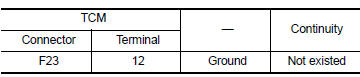
Is the inspection result normal? YES >> GO TO 2.
NO >> Repair or replace malfunctioning part.
2.CHECK CVT FLUID TEMPERATURE SENSOR
Check CVT fluid temperature sensor. Refer to TM-174, "Component Inspection".
Is the inspection result normal? YES >> Check intermittent incident. Refer to GI-39, "Intermittent Incident".
NO >> Repair or replace malfunctioning parts.
Component Inspection
1.CHECK CVT FLUID TEMPERATURE SENSOR
Check resistance between CVT unit connector terminals.
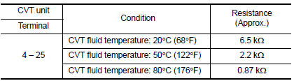
Is the inspection result normal? YES >> INSPECTION END
NO >> There is a malfunction of CVT fluid temperature sensor. Replace transaxle assembly. Refer to TM-283, "Removal and Installation".
 P0711 Transmission fluid temperature sensor A
DTC Logic
DTC DETECTION LOGIC
DTC
CONSULT screen terms
(Trouble diagnosis content)
DTC detection condition
Possible causes
P0711
FLUID TEMP SENSOR A
(Transmission F ...
 P0713 Transmission fluid temperature sensor A
DTC Logic
DTC DETECTION LOGIC
DTC
CONSULT screen terms
(Trouble diagnosis content)
DTC detection condition
Possible causes
P0713
FLUID TEMP SENSOR A
(Transmission ...
Other materials:
B1431, B1433 Seat belt pre-tensioner RH
Description
DTC B1431, B1433 SEAT BELT PRE-TENSIONER RH
The seat belt pre-tensioner RH is wired to the air bag diagnosis sensor unit.
The air bag diagnosis sensor unit
will monitor for opens and shorts in detected lines to the seat belt pre-tensioner
RH.
PART LOCATION
Refer to SRC-5, " ...
Oil seal
Valve oil seal : Removal and Installation
REMOVAL
Rotate crankshaft, and set piston whose valve oil seal is to be removed
to TDC. This will prevent valve
from dropping into cylinder.
CAUTION:
When rotating crankshaft, be careful to avoid scarring front cover with
timing chain.
Re ...
Tire Pressure Monitoring System (TPMS)
Each tire, including the spare (if provided),
should be checked monthly when cold and inflated
to the inflation pressure recommended by
the vehicle manufacturer on the vehicle placard
or tire inflation pressure label. (If your vehicle has
tires of a different size than the size indicated on
th ...
