Nissan Sentra Service Manual: P0705 Transmission range sensor A
DTC Logic
DTC DETECTION LOGIC
| DTC | CONSULT screen terms [Trouble diagnosis content] | DTC detection condition | Possible causes |
| P0705 | T/M RANGE SENSOR A [Transmission Range Sensor A Circuit (PRNDL Input)] | Two or more range signals simultaneously
stay ON continuously for 5 seconds under the
following diagnosis condition 1 and 2:
|
|
DTC CONFIRMATION PROCEDURE
CAUTION:
Be careful of the driving speed.
1.PREPARATION BEFORE WORK
If another “DTC CONFIRMATION PROCEDURE” occurs just before, turn ignition switch OFF and wait for at least 10 seconds, then perform the next test.
>> GO TO 2.
2.CHECK DTC DETECTION
- Start the engine.
- Maintain the following conditions.
Accelerator pedal position : 0.0/8
Brake pedal : Depressed
Vehicle speed : 0 km/h (0 MPH)
- Shift the selector lever through entire positions from “P” to “L”. (Hold the selector lever at each position for 10 seconds or more.)
- Check the first trip DTC.
Is “P0705” detected? YES >> Go to TM-161, "Diagnosis Procedure".
NO >> INSPECTION END
Diagnosis Procedure
1.CHECK TCM INPUT SIGNALS
 With CONSULT
- Turn ignition switch ON.
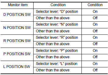
- Select “Data Monitor” in “TRANSMISSION”.
- Select “D POSITION SW”, “N POSITION SW”, “R POSITION SW”, “P POSITION SW” and “L POSITION SW”.
- Shift selector lever through entire positions from “P” to “L” and check ON/OFF of each monitor item.
 Without CONSULT
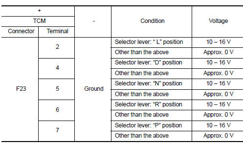
- Turn ignition switch OFF.
- Disconnect TCM connector.
- Turn ignition switch ON.
- Shift selector lever from “P” to “L” and check voltage between TCM harness connector terminals and ground.
Is the check result normal? YES >> Check intermittent incident. Refer to GI-39, "Intermittent Incident".
NO-1 [“D POSITION SW” is “ON” when selector is not in “D” position. (Or connector terminal 4 is at power voltage.)]>>GO TO 2.
NO-2 [“N POSITION SW” is “ON” when selector is not in “N” position. (Or connector terminal 5 is at power voltage.)]>>GO TO 4.
NO-3 [“R POSITION SW” is “ON” when selector is not in “R” position. (Or connector terminal 6 is at power voltage.)]>>GO TO 6.
NO-4 [“P POSITION SW” is “ON” when selector is not in “P” position. (Or connector terminal 7 is at power voltage.)]>>GO TO 8.
NO-5 [“L POSITION SW” is “ON” when selector is not in “L” position. (Or connector terminal 2 is at power voltage.)]>>GO TO 10.
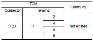
2.CHECK D POSITION SW CIRCUIT (PART 1)
- Turn ignition switch OFF.
- Disconnect TCM connector.
- Check continuity between TCM harness connector terminals.
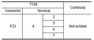
Is the check result normal? YES >> GO TO 3.
NO >> Repair or replace malfunctioning parts.
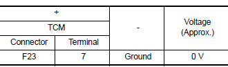
3.CHECK D POSITION SW CIRCUIT (PART 2)
- Disconnect transmission range switch connector.
- Turn ignition switch ON.
- Check voltage between TCM harness connector terminal and ground.
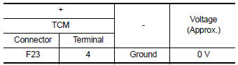
Is the check result normal? YES >> GO TO 12.
NO >> Repair or replace malfunctioning parts.
4.CHECK N POSITION SW CIRCUIT (PART 1)
- Turn ignition switch OFF.
- Disconnect TCM connector.
- Check continuity between TCM harness connector terminals.
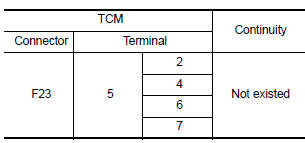
Is the check result normal? YES >> GO TO 5.
NO >> Repair or replace malfunctioning parts.
5.CHECK N POSITION SW CIRCUIT (PART 2)
- Disconnect transmission range switch connector.
- Turn ignition switch ON.
- Check voltage between TCM harness connector terminal and ground.
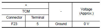
Is the check result normal? YES >> GO TO 12.
NO >> Repair or replace malfunctioning parts.
6.CHECK R POSITION SW CIRCUIT (PART1)
- Turn ignition switch OFF.
- Disconnect TCM connector.
- Check continuity between TCM harness connector terminals.
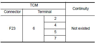
Is the check result normal? YES >> GO TO 7.
NO >> Repair or replace malfunctioning parts.
7.CHECK R POSITION SW CIRCUIT (PART 2)
- Disconnect transmission range switch connector
- Turn ignition switch ON.
- Check voltage between TCM harness connector terminal and ground.
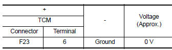
Is the check result normal? YES >> GO TO 12.
NO >> Repair or replace malfunctioning parts.
8.CHECK P POSITION SW CIRCUIT (PART 1)
- Turn ignition switch OFF
- Disconnect TCM connector.
- Check continuity between TCM harness connector terminals.
Is the check result normal? YES >> GO TO 9.
NO >> Repair or replace malfunctioning parts.
9.CHECK P POSITION SW CIRCUIT (PART 2)
- Disconnect transmission range switch connector.
- Turn ignition switch ON.
- Check voltage between TCM harness connector terminal and ground.
Is the check result normal? YES >> GO TO 12.
NO >> Repair or replace malfunctioning parts.
10.CHECK L POSITION SWITCH CIRCUIT (PART 1)
- Turn ignition switch OFF.
- Disconnect TCM connector.
- Check continuity between TCM harness connector terminals.
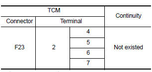
Is the check result normal? YES >> GO TO 11.
NO >> Repair or replace malfunctioning parts.
11.CHECK L POSITION SWITCH CIRCUIT (PART 2)
- Disconnect transmission range switch connector.
- Turn ignition switch ON.
- Check voltage between TCM harness connector terminal and ground.
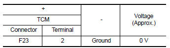
Is the check result normal? YES >> GO TO 12.
NO >> Repair or replace malfunctioning parts.
12.CHECK TRANSMISSION RANGE SWITCH
Check transmission range switch. Refer to TM-165, "Component Inspection".
Is the check result normal? YES >> Check intermittent incident. Refer to GI-39, "Intermittent Incident".
NO >> Repair or replace malfunctioning parts.
Component Inspection
1.CHECK TRANSMISSION RANGE SWITCH
Check continuity between transmission range switch connector terminals.
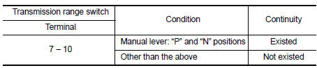
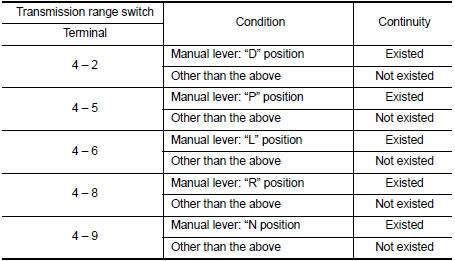
Is the inspection result normal? YES >> INSPECTION END
NO >> There is a malfunction of transmission range switch. Replace transaxle assembly. Refer to TM- 283, "Removal and Installation".
 P062F Eeprom
DTC Logic
DTC DETECTION LOGIC
DTC
CONSULT screen terms
(Trouble diagnosis content)
DTC detection condition
Possible causes
P062F
EEPROM
(Internal Control Module EE ...
 P0706 Transmission range sensor A
DTC Logic
DTC DETECTION LOGIC
DTC
CONSULT screen terms
(Trouble diagnosis content)
DTC detection condition
Possible causes
P0706
T/M RANGE SENSOR A
(Transmission R ...
Other materials:
P1551, P1552 Battery current sensor
DTC Logic
DTC DETECTION LOGIC
DTC No.
CONSULT screen terms
(Trouble diagnosis content)
DTC detecting condition
Possible cause
P1551
BAT CURRENT SENSOR
(Battery current sensor)
An excessively low voltage from the sensor
is sent to ECM.
Harness or ...
Towing a trailer
Do not tow a trailer with your vehicle.
Flat towing
Towing your vehicle with all four wheels on the
ground is sometimes called flat towing. This
method is sometimes used when towing a vehicle
behind a recreational vehicle, such as a motor
home.
CAUTION
Failure to follow these guidelines c ...
Increasing fuel economy
Keep your engine tuned up.
Follow the recommended scheduled maintenance.
Keep the tires inflated to the correct pressure.
Low tire pressure increases tire wear
and lowers fuel economy.
Keep the wheels in correct alignment. Improper
alignment increases tire wear and
lowers fuel eco ...
