Nissan Sentra Service Manual: P0335 CKP Sensor (POS)
DTC Logic
DTC DETECTION LOGIC
NOTE:
If DTC P0340 is displayed with DTC P0643, first perform the trouble diagnosis for DTC P0643. Refer to EC- 353, "DTC Logic".
| DTC No. | CONSULT screen terms (Trouble diagnosis content) | DTC detecting condition | Possible cause |
| P0335 | CKP SEN/CIRCUIT (Crankshaft position sensor “A” circuit) |
|
|
DTC CONFIRMATION PROCEDURE
1.PRECONDITIONING
If DTC Confirmation Procedure has been previously conducted, always perform the following procedure before conducting the next test.
- Turn ignition switch OFF and wait at least 10 seconds.
- Turn ignition switch ON.
- Turn ignition switch OFF and wait at least 10 seconds.
TESTING CONDITION:
Before performing the following procedure, confirm that battery voltage is more than 10.5 V with ignition switch ON.
>> GO TO 2.
2.PERFORM DTC CONFIRMATION PROCEDURE
- Start engine and let it idle for at least 5 seconds.
If engine does not start, crank engine for at least 2 seconds.
- Check 1st trip DTC.
Is 1st trip DTC detected? YES >> Proceed to EC-277, "Diagnosis Procedure".
NO >> INSPECTION END
Diagnosis Procedure
1.CHECK CRANKSHAFT POSITION (CKP) SENSOR (POS) POWER SUPPLY
- Disconnect crankshaft position (CKP) sensor (POS) harness connector.
- Turn ignition switch ON.
- Check the voltage between CKP sensor (POS) harness connector and ground.
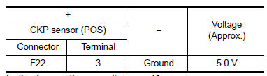
Is the inspection result normal? YES >> GO TO 3.
NO >> GO TO 2.
2.CHECK CKP SENSOR (POS) POWER SUPPLY CIRCUIT
- Turn ignition switch OFF
- Disconnect ECM harness connector.
- Check the continuity between CKP sensor (POS) harness connector and ECM harness connector.
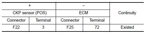
- Also check harness for short to ground.
Is the inspection result normal? YES >> Perform the trouble diagnosis for power supply circuit.
NO >> Repair or replace error-detected parts.
3.CHECK CKP SENSOR (POS) GROUND CIRCUIT
- Turn ignition switch OFF.
- Disconnect ECM harness connector
- Check the continuity between CKP sensor (POS) harness connector and ECM harness connector.
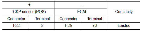
- Also check harness for short to power
Is the inspection result normal? YES >> GO TO 4.
NO >> Repair or replace error-detected parts.
4.CHECK CKP SENSOR (POS) INPUT SIGNAL CIRCUIT
- Check the continuity between CKP sensor (POS) harness connector and ECM harness connector.
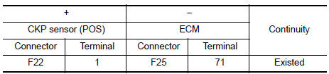
- Also check harness for short to ground and to power.
Is the inspection result normal? YES >> GO TO 5.
NO >> Repair or replace error-detected parts.
5.CHECK CRANKSHAFT POSITION SENSOR (POS)
Check the crankshaft position sensor (POS). Refer to EC-279, "Component Inspection [CKP Sensor (POS)]".
Is the inspection result normal? YES >> GO TO 6.
NO >> Replace crankshaft position sensor (POS). Refer to EM-33, "Exploded View".
6.CHECK GEAR TOOTH
- Remove crankshaft position sensor (POS). Refer to EM-33, "Exploded View".
- Look into the mounting hole
 of
of
the crankshaft position sensor (POS) to check that there is no missing gear tooth in the signal plate 1.
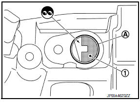
Is the inspection result normal? YES >> Check intermittent incident. Refer to GI-39, "Intermittent Incident".
NO >> Replace the signal plate. Refer to EM-90, "Exploded View" (M/T) or EM-92, "Exploded View" (CVT).
Component Inspection [CKP Sensor (POS)]
1.CHECK CRANKSHAFT POSITION SENSOR (POS)-1
- Turn ignition switch OFF.
- Loosen the fixing bolt of the sensor.
- Disconnect crankshaft position sensor (POS) harness connector.
- Remove the sensor.
- Visually check the sensor for chipping.
Is the inspection result normal? YES >> GO TO 2.
NO >> Replace crankshaft position sensor (POS). Refer to EM- 33, "Exploded View".
2.CHECK CRANKSHAFT POSITION SENSOR (POS)-2
Check the resistance between crankshaft position sensor (POS) terminals as per the following.
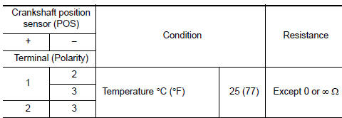
Is the inspection result normal? YES >> INSPECTION END
NO >> Replace crankshaft position sensor (POS). Refer to EM-33, "Exploded View".
 P0327, P0328 KS
DTC Logic
DTC DETECTION LOGIC
DTC No.
CONSULT screen terms
(Trouble diagnosis content)
DTC detecting condition
Possible cause
P0327
KNOCK SEN/CIRC-B1
(Knock sensor ...
 P0340 CMP Sensor (PHASE)
DTC Logic
DTC DETECTION LOGIC
DTC No.
CONSULT screen terms
(Trouble diagnosis content)
DTC detecting condition
Possible cause
P0340
CMP SEN/CIRC-B1
(Camshaft positi ...
Other materials:
Rear seat
Exploded View
Rear seatback assembly (RH)
Seatback striker
Seatback latch release knob
Seatback latch assembly
Seatback silencer (RH)
Rear seatback frame (RH)
Seatback latch release knob finisher
Rear seat bolster trim (RH)
Rear seat bolster pad (RH)
Rear seat bolster (RH)
...
System description
COMPONENT PARTS
Component Part Location
ECM
IPDM E/R
BCM (view with combination meter
removed)
A/C auto amp. (view with A/C switch
assembly removed)
A/C switch assembly
A/C Compressor
Refrigerant pressure sensor (view
with front bumper fascia removed)
Fuse Block (J/ ...
The parking brake release warning
continues sounding, or does not
sound
Description
The parking brake warning buzzer sounds continuously during vehicle
travel though the parking brake is
released.
The parking brake warning buzzer does not sound at all even though
driving the vehicle with the parking
brake applied.
Diagnosis procedure
1.Check parking ...
