Nissan Sentra Service Manual: P0130 A/F Sensor 1
DTC Logic
DTC DETECTION LOGIC
To judge the malfunction, the diagnosis checks that the A/F signal computed by ECM from the A/F sensor 1 signal fluctuates according to fuel feedback control.
| DTC No. | CONSULT screen terms (Trouble diagnosis content) | DTC detecting condition | Possible cause | |
| P0130 | A/F SENSOR1 (B1) (O2 sensor circuit bank 1 sensor 1) | A) | The A/F signal computed by ECM from the A/F sensor 1 signal is constantly in the range other than approx. 2.2 V. |
|
| B) | The A/F signal computed by ECM from the A/F sensor 1 signal is constantly approx. 2.2 V. | |||
DTC CONFIRMATION PROCEDURE
1.PRECONDITIONING
- If DTC Confirmation Procedure has been previously conducted, always perform the following procedure before conducting the next test.
- Turn ignition switch OFF and wait at least 10 seconds.
- Turn ignition switch ON.
- Turn ignition switch OFF and wait at least 10 seconds.
TESTING CONDITION:
Before performing the following procedure, confirm that battery voltage is more than 11 V at idle.
>> GO TO 2.
2.PERFORM DTC CONFIRMATION PROCEDURE FOR MALFUNCTION A
 With CONSULT
- Start engine and warm it up to normal operating temperature.
- Let it idle for 2 minutes.
- Check 1st trip DTC.
Is 1st trip DTC detected? YES >> Proceed to EC-211, "Diagnosis Procedure".
NO-1 (  With CONSULT)>>GO TO 3.
NO-2 (  Without CONSULT)>>GO TO 7.
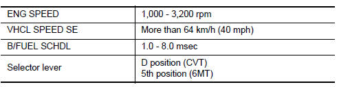
3.CHECK AIR FUEL RATIO (A/F) SENSOR 1 FUNCTION
- Select “A/F SEN1 (B1)” in “DATA MONITOR” mode of “ENGINE” using CONSULT.
- Check “A/F SEN1 (B1)” indication.
Does the indication fluctuates around 2.2 V? YES >> GO TO 4.
NO >> Proceed to EC-211, "Diagnosis Procedure".
4.PERFORM DTC CONFIRMATION PROCEDURE FOR MALFUNCTION B-1
- Select “A/F SEN1 (B1) P1276” of “A/F SEN1” in “DTC WORK SUPPORT” mode of “ENGINE” using CONSULT.
- Touch “START”.
- When the following conditions are met, “TESTING” will be displayed on the CONSULT screen.
If “TESTING” is not displayed after 20 seconds, retry from step 2.
CAUTION:
Always drive vehicle at a safe speed.
Is “TESTING” displayed on CONSULT screen? YES >> GO TO 5.
NO >> 1. Check A/F sensor 1 function again.
2. GO TO 3.
5.PERFORM DTC CONFIRMATION PROCEDURE FOR MALFUNCTION B-2
Release accelerator pedal fully.
NOTE:
Never apply brake during releasing the accelerator pedal.
Which does “TESTING” change to? COMPLETED>>GO TO 6.
OUT OF CONDITION>>1.Retry DTC CONFIRMATION PROCEDURE.
2. GO TO 4.
6.PERFORM DTC CONFIRMATION PROCEDURE FOR MALFUNCTION B-3
Touch “SELF-DIAG RESULT” Which is displayed on CONSULT screen? YES >> INSPECTION END
NO >> Proceed to EC-211, "Diagnosis Procedure".
7.PERFORM COMPONENT FUNCTION CHECK FOR MALFUNCTION B
Perform Component Function Check. Refer to EC-211, "Component Function Check".
NOTE:
Use component function check to check the overall function of the A/F sensor 1 circuit. During this check, a 1st trip DTC might not be confirmed.
Is the inspection result normal? YES >> INSPECTION END
NO >> Proceed to EC-211, "Diagnosis Procedure".
Component Function Check
1.PERFORM COMPONENT FUNCTION CHECK
 With GST
- Start engine and warm it up to normal operating temperature.
- Drive the vehicle at a speed of 80 km/h (50 MPH) for a few minutes in the suitable gear position.
- Shift the selector lever to the D position (CVT) or 5th position (M/T), then release the accelerator pedal fully until the vehicle speed decreases to 50 km/h (31 MPH).
CAUTION:
Always drive vehicle at a safe speed.
NOTE:
Never apply brake during releasing the accelerator pedal.
- Repeat steps 2 to 3 for five times.
- Stop the vehicle and turn ignition switch OFF.
- Wait at least 10 seconds and restart engine.
- Repeat steps 2 to 3 for five times
- Stop the vehicle.
- Check 1st trip DTC.
Is 1st trip DTC detected? YES >> Proceed to EC-211, "Diagnosis Procedure".
NO >> INSPECTION END
Diagnosis Procedure
1.CHECK AIR FUEL RATIO (A/F) SENSOR 1 POWER SUPPLY
- Turn ignition switch OFF.
- Disconnect A/F sensor 1 harness connector.
- Turn ignition switch ON.
- Check the voltage between A/F sensor 1 harness connector and ground.
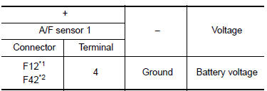
*1: Except California
*2: For California
Is the inspection result normal? YES >> GO TO 3.
NO >> GO TO 2.
2.CHECK AIR FUEL RATIO (A/F) SENSOR 1 POWER SUPPLY CIRCUIT
- Turn ignition switch OFF.
- Disconnect IPDM E/R harness connector
- Check the continuity between A/F sensor 1 harness connector and IPDM E/R harness connector.
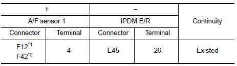
*1: Except California
*2: For California
- Also check harness for short to ground.
Is the inspection result normal? YES >> Perform the trouble diagnosis for power supply circuit.
NO >> Repair or replace error-detected parts.
3.CHECK A/F SENSOR 1 INPUT SIGNAL CIRCUIT
- Turn ignition switch OFF.
- Disconnect ECM harness connector.
- Check the continuity between A/F sensor 1 harness connector and ECM harness connector.
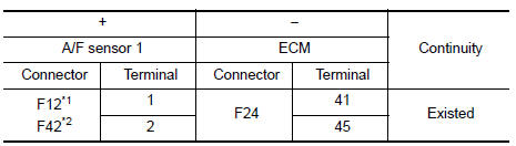
*1: Except California
*2: For California
- Check the continuity between A/F sensor 1 harness connector and ground, or ECM harness connector and ground.
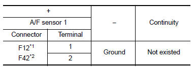
*1: Except California
*2: For California
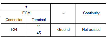
- Also check harness for short to power.
Is the inspection result normal? YES >> GO TO 4.
NO >> Repair or replace error-detected parts.
4.CHECK INTERMITTENT INCIDENT
Check intermittent incident. Refer to GI-39, "Intermittent Incident".
Is the inspection result normal? YES >> Replace air fuel ratio (A/F) sensor 1. Refer to EM-30, "Exploded View".
NO >> Repair or replace error-detected parts.
 P0128 Thermostat function
DTC Logic
DTC DETECTION LOGIC
NOTE:
If DTC P0128 is displayed with DTC P0300, P0301, P0302, P0303 or P0304,
first perform the trouble
diagnosis for P0300, P0301, P0302, P0303 or P0304. Refer to ...
 P0131 A/F Sensor 1
DTC Logic
DTC DETECTION LOGIC
To judge the malfunction, the diagnosis checks that the A/F signal computed
by ECM from the A/F sensor 1
signal is not inordinately low.
DTC No.
CONSULT s ...
Other materials:
Door handle
Front door handle
Front door handle : exploded view
Outside handle bracket
Front gasket
Outside handle
Intelligent key button
Door key cylinder rod
Inside handle assembly
Rear gasket
Front door handle : removal and installation - inside handle
REMOVAL
Remove front door ...
Main line between ipdm-e and dlc
circuit
Diagnosis procedure
1.Check connector
Turn the ignition switch off.
Disconnect the battery cable from the negative terminal.
Check the following terminals and connectors for damage, bend and loose
connection (connector side
and harness side).
Harness connector E4
Harness connec ...
Cooling fan
Component Function Check
1.CHECK COOLING FAN FUNCTION
With CONSULT
Turn ignition switch ON.
Perform “FAN” in “ACTIVE TEST” mode of “ENGINE” using CONSULT
Check that cooling fan operates at low speed or high speed.
Without CONSULT
Activate IPDM E/R auto ...
