Nissan Sentra Service Manual: P0112, P0113 IAT Sensor
DTC Logic
DTC DETECTION LOGIC
| DTC No. | CONSULT screen terms (Trouble diagnosis content) | DTC detecting condition | Possible cause |
| P0112 | IAT SEN/CIRCUIT- B1 (Intake air temperature sensor 1 circuit low bank 1) | An excessively low voltage from the intake air temperature sensor is sent to ECM. |
|
| P0113 | IAT SEN/CIRCUIT- B1 (Intake air temperature sensor 1 circuit high bank 1) | An excessively high voltage from the intake air temperature sensor is sent to ECM. |
DTC CONFIRMATION PROCEDURE
1.PRECONDITIONING
If DTC Confirmation Procedure has been previously conducted, always perform the following procedure before conducting the next test
- Turn ignition switch OFF and wait at least 10 seconds.
- Turn ignition switch ON.
- Turn ignition switch OFF and wait at least 10 seconds.
>> GO TO 2.
2.PERFORM DTC CONFIRMATION PROCEDURE
- Turn ignition switch ON and wait at least 5 seconds.
- Check 1st trip DTC.
Is 1st trip DTC detected? YES >> Proceed to EC-194, "Diagnosis Procedure".
NO >> INSPECTION END
Diagnosis Procedure
1.CHECK INTAKE AIR TEMPERATURE SENSOR POWER SUPPLY
- Turn ignition switch OFF.
- Disconnect mass air flow sensor (with intake air temperature sensor) harness connector.
- Turn ignition switch ON.
- Check the voltage between mass air flow sensor harness connector and ground.
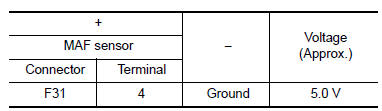
Is the inspection result normal? YES >> GO TO 3.
NO >> GO TO 2.
2.CHECK INTAKE AIR TEMPERATURE SENSOR POWER SUPPLY CIRCUIT
- Turn ignition switch OFF.
- Disconnect ECM harness connector
- Check the continuity between mass air flow sensor harness connector and ECM harness connector.
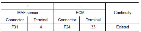
- Also check harness for short to ground.
Is the inspection result normal? YES >> Perform the trouble diagnosis for power supply circuit.
NO >> Repair or replace error-detected parts.
3.CHECK INTAKE AIR TEMPERATURE SENSOR GROUND CIRCUIT
- Turn ignition switch OFF.
- Disconnect ECM harness connector.
- Check the continuity between mass air flow sensor harness connector and ECM harness connector.
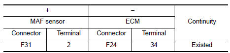
- Also check harness for short to power.
Is the inspection result normal? YES >> GO TO 4.
NO >> Repair or replace error-detected parts.
4.CHECK INTAKE AIR TEMPERATURE SENSOR
Check the intake air temperature sensor. Refer to EC-195, "Component Inspection (IAT Sensor)".
Is the inspection result normal? YES >> Check intermittent incident. Refer to GI-39, "Intermittent Incident".
NO >> Replace mass air flow sensor (with intake air temperature sensor). Refer to EM-25, "Exploded View".
Component Inspection (IAT Sensor)
1.CHECK INTAKE AIR TEMPERATURE SENSOR
- Turn ignition switch OFF.
- Disconnect mass air flow sensor harness connector and reconnect it again.
- Turn ignition switch ON.
- On CONSULT screen, select “ENGINE” >> “DATA MONITOR” >> “INT/A TEMP SEN”.
- Check that the indicated value of “INT/A TEMP SEN” is almost the same as intake air temperature.
Is the inspection result normal? YES >> INSPECTION END
NO >> Replace mass air flow sensor (with intake air temperature sensor). Refer to EM-25, "Exploded View".
 P0111 IAT Sensor
DTC Logic
DTC DETECTION LOGIC
DTC No.
CONSULT screen terms
(Trouble diagnosis content)
DTC detecting condition
Possible cause
P0111
IAT SENSOR 1 B1
(Intake air temp ...
 P0116 ECT Sensor
DTC Logic
DTC DETECTION LOGIC
DTC No.
CONSULT screen terms
(Trouble diagnosis content)
DTC detecting condition
Possible cause
P0116
ECT SEN/CIRC
(Engine coolant tem ...
Other materials:
Symptom diagnosis
Squeak and rattle trouble diagnoses
Work Flow
Customer interview
Interview the customer if possible, to determine the conditions that exist
when the noise occurs. Use the Diagnostic
Worksheet during the interview to document the facts and conditions when the
noise occurs and any
custome ...
The ambient temperature display is incorrect
Description
The displayed outside air temperature is higher than the actual
temperature.
The displayed outside air temperature is lower than the actual
temperature.
Outside air temperature is not indicated.
Diagnosis procedure
1.Check ambient sensor signal circuit
Check the ambie ...
Removal and installation
Hood
Hood assembly
Hood assembly : exploded view
Hood hinge (LH/RH)
Hood assembly
Hood bumper rubber
Hood seal
Hood insulator
Hood support rod
Hood support rod clamp
Clip
Hood assembly : removal and installation
CAUTION:
Use two people when removing or installin ...
