Nissan Sentra Service Manual: P0101, P0102, P0103 MAF Sensor
DTC Logic
DTC DETECTION LOGIC
| DTC No. | CONSULT screen terms (Trouble diagnosis content) | DTC detecting condition | Possible cause |
| P0101 | MAF SEN/CIRCUIT-B1 (Mass or volume air flow “A” circuit range/performance) | An excessively high voltage from the mass air flow sensor is sent to ECM. |
|
| P0102 | MAF SEN/CIRCUIT-B1 (Mass or volume air flow “A” circuit low input) | An excessively low voltage from the mass air flow sensor is sent to ECM. |
|
| P0103 | MAF SEN/CIRCUIT-B1 (Mass or volume air flow “A” circuit high input) | An excessively high voltage from the mass air flow sensor is sent to ECM. |
|
DTC CONFIRMATION PROCEDURE
1.PRECONDITIONING
If DTC Confirmation Procedure has been previously conducted, always perform the following procedure before conducting the next test.
- Turn ignition switch OFF and wait at least 10 seconds.
- Turn ignition switch ON.
- Turn ignition switch OFF and wait at least 10 seconds.
Which DTC is detected? P0102 >> GO TO 2.
P0101 or P0103>>GO TO 3.
2.PERFORM DTC CONFIRMATION PROCEDURE FOR DTC P0102
- Start engine and wait at least 5 seconds.
- Check DTC.
Is DTC detected? YES >> Proceed to EC-187, "Diagnosis Procedure".
NO >> INSPECTION END
3.PERFORM DTC CONFIRMATION PROCEDURE FOR DTC P0101 AND P0103-1
- Turn ignition switch ON and wait at least 5 seconds.
- Check DTC.
Is DTC detected? YES >> Proceed to EC-187, "Diagnosis Procedure".
NO >> GO TO 4.
4.PERFORM DTC CONFIRMATION PROCEDURE FOR DTC P0101 AND P0103-2
- Start engine and wait at least 5 seconds.
- Check DTC.
Is DTC detected? YES >> Proceed to EC-187, "Diagnosis Procedure".
NO >> INSPECTION END
Diagnosis Procedure
1.INSPECTION START
Confirm the detected DTC.
Which DTC is detected? P0102 >> GO TO 2.
P0101 and P0103>>GO TO 3.
2.CHECK INTAKE SYSTEM
Check the following for connection.
- Air duct
- Vacuum hoses
- Intake air passage between air duct to intake manifold
Is the inspection result normal? YES >> GO TO 3.
NO >> Reconnect or replace error-detected parts.
3.CHECK MASS AIR FLOW (MAF) SENSOR POWER SUPPLY
- Turn ignition switch OFF
- Disconnect MAF sensor harness connector.
- Turn ignition switch ON.
- Check the voltage between MAF sensor harness connector and ground.
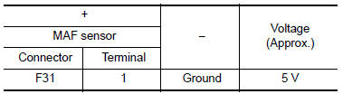
Is the inspection result normal? YES >> GO TO 4.
NO >> GO TO 7.
4.CHECK MAF SENSOR GROUND CIRCUIT
- Turn ignition switch OFF.
- Disconnect ECM harness connector.
- Check the continuity between MAF sensor harness connector and ECM harness connector.
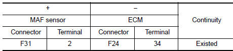
- Also check harness for short to power.
Is the inspection result normal? YES >> GO TO 5.
NO >> Repair or replace error-detected parts.
5.CHECK MAF SENSOR INPUT SIGNAL CIRCUIT
- Check the continuity between MAF sensor harness connector and ECM harness connector.

- Also check harness for short to ground and short to power.
Is the inspection result normal? YES >> GO TO 6.
NO >> Repair or replace error-detected parts
6.CHECK MAF SENSOR
Check the MAF sensor. Refer to EC-188, "Component Inspection (MAF Sensor)".
Is the inspection result normal? YES >> Check intermittent incident. Refer to GI-39, "Intermittent Incident".
NO >> Replace MAF sensor (with intake air temperature sensor). Refer to EM-25, "Exploded View".
7.CHECK MAF SENSOR POWER CIRCUIT
- Turn ignition switch OFF.
- Disconnect ECM harness connector.
- Check the continuity between MAF sensor harness connector and ECM harness connector.

- Also check harness for short to power and short to ground.
Is the inspection result normal? YES >> GO TO 8.
NO >> Repair or replace error-detected parts.
8.CHECK SENSOR POWER SUPPLY 2 CIRCUIT
Check sensor power supply 2 circuit. Refer to EC-444, "Diagnosis Procedure".
Is inspection result normal? YES >> Perform the trouble diagnosis for power supply circuit.
NO >> Repair or replace error-detected parts.
Component Inspection (MAF Sensor)
1.CHECK MASS AIR FLOW SENSOR-1
 With CONSULT
- Turn ignition switch OFF.
- Reconnect all harness connectors disconnected.
- Start engine and warm it up to normal operating temperature
- Connect CONSULT and select “DATA MONITOR” mode of “ENGINE”.
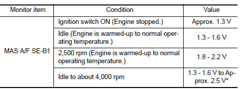
- Select “MAS A/F SE-B1” and check indication.
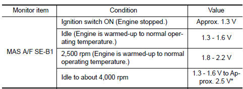
*: Check for linear voltage rise in response to engine being increased to about 4,000 rpm.
 Without CONSULT
- Turn ignition switch OFF.
- Reconnect all harness connectors disconnected.
- Start engine and warm it up to normal operating temperature.
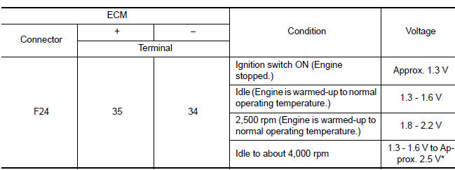
- Check the voltage between ECM harness connector and ground.
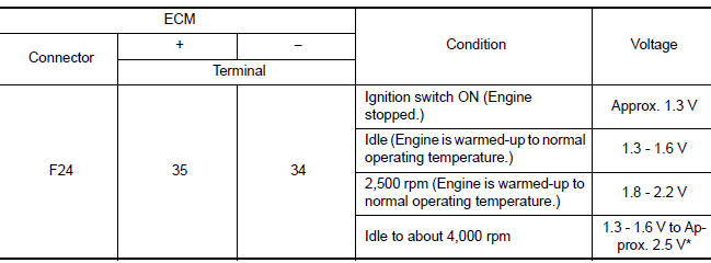
*: Check for linear voltage rise in response to engine being increased to about 4,000 rpm.
Is the inspection result normal? YES >> INSPECTION END
NO >> GO TO 2.
2.CHECK FOR THE CAUSE OF UNEVEN AIR FLOW THROUGH MASS AIR FLOW SENSOR
- Turn ignition switch OFF.
- Check for the cause of uneven air flow through mass air flow sensor. Refer to the following.
- Crushed air ducts
- Malfunctioning seal of air cleaner element
- Uneven dirt of air cleaner element
- Intake valve deposits
- Improper specification of intake air system parts
Is the inspection result normal? YES >> GO TO 4.
NO >> GO TO 3.
3.CHECK MASS AIR FLOW SENSOR-2
 With CONSULT
- Repair or replace malfunctioning part
- Start engine and warm it up to normal operating temperature
- Connect CONSULT and select “DATA MONITOR” mode of “ENGINE”.
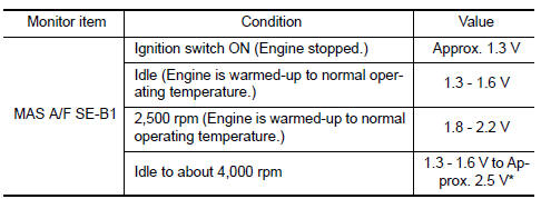
- Select “MAS A/F SE-B1” and check indication.
*: Check for linear voltage rise in response to engine being increased to about 4,000 rpm.
 Without CONSULT
- Repair or replace malfunctioning part.
- Start engine and warm it up to normal operating temperature.
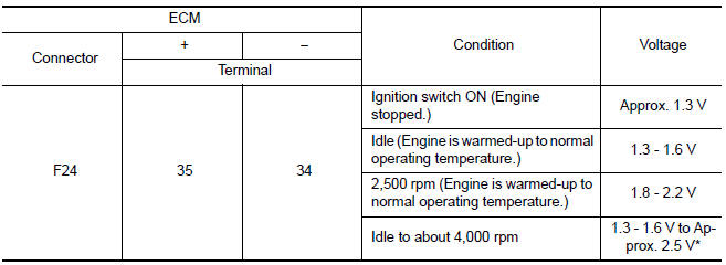
- Check the voltage between ECM harness connector and ground.
*: Check for linear voltage rise in response to engine being increased to about 4,000 rpm.
Is the inspection result normal? YES >> INSPECTION END
NO >> GO TO 4.
4.CHECK MASS AIR FLOW SENSOR-3
 With CONSULT
- Turn ignition switch OFF.
- Disconnect mass air flow sensor harness connector and reconnect it again.
- Start engine and warm it up to normal operating temperature.
- Connect CONSULT and select “DATA MONITOR” mode of “ENGINE”.
- Select “MAS A/F SE-B1” and check indication.
*: Check for linear voltage rise in response to engine being increased to about 4,000 rpm.
 Without CONSULT
- Turn ignition switch OFF.
- Disconnect mass air flow sensor harness connector and reconnect it again.
- Start engine and warm it up to normal operating temperature
- Check the voltage between ECM harness connector and ground.
*: Check for linear voltage rise in response to engine being increased to about 4,000 rpm.
Is the inspection result normal?
YES >> INSPECTION END
NO >> Clean or replace mass air flow sensor. Refer to EM-25, "Exploded View".
 P0078 EVT Control solenoid valve
DTC Logic
DTC DETECTION LOGIC
DTC No.
CONSULT screen terms
(Trouble diagnosis content)
DTC detecting condition
Possible cause
P0078
EX V/T ACT/CIRC-B1
(Exhaust valv ...
 P0111 IAT Sensor
DTC Logic
DTC DETECTION LOGIC
DTC No.
CONSULT screen terms
(Trouble diagnosis content)
DTC detecting condition
Possible cause
P0111
IAT SENSOR 1 B1
(Intake air temp ...
Other materials:
Brake fluid
Drain and Refill
CAUTION:
Do not spill or splash brake fluid on painted surfaces. Brake
fluid may damage paint. If brake fluid is
splashed on painted areas, wash it away with water immediately.
Prior to repair, turn the ignition switch OFF, disconnect the ABS
actuator and electric uni ...
Parking brake
WARNING
Be sure the parking brake is fully released
before driving. Failure to do so
can cause brake failure and lead to an
accident.
Do not release the parking brake from
outside the vehicle.
Do not use the shift lever in place of the
parking brake. When parki ...
Preparation
Special Service Tool
The actual shape of the tools may differ from those illustrated here.
Commercial Service Tool
...
