Nissan Sentra Service Manual: P0031, P0032 A/F sensor 1 Heater
DTC Logic
DTC DETECTION LOGIC
| DTC No. | CONSULT screen terms (Trouble diagnosis content) | DTC detecting condition | Possible cause |
| P0031 | A/F SEN 1 HTR (B1) (HO2S heater control circuit low bank 1 sensor 1) | The current amperage in the A/F sensor 1 heater
circuit is out of the normal range.
(An excessively low voltage signal is sent to ECM through the A/F sensor 1 heater.) |
|
| P0032 | A/F SEN 1 HTR (B1) (HO2S heater control circuit high bank 1 sensor 1) | The current amperage in the A/F sensor 1 heater
circuit is out of the normal range.
(An excessively high voltage signal is sent to ECM through the A/F sensor 1 heater.) |
|
DTC CONFIRMATION PROCEDURE
1.PRECONDITIONING
If DTC Confirmation Procedure has been previously conducted, always perform the following procedure before conducting the next test.
- Turn ignition switch OFF and wait at least 10 seconds.
- Turn ignition switch ON.
- Turn ignition switch OFF and wait at least 10 seconds.
TESTING CONDITION:
Before performing the following procedure, confirm that battery voltage is more than between 11 V at idle.
>> GO TO 2.
2.PERFORM DTC CONFIRMATION PROCEDURE
- Start engine and let it idle for at least 10 seconds.
- Check 1st trip DTC.
Is 1st trip DTC detected? YES >> Proceed to EC-176, "Diagnosis Procedure".
NO >> INSPECTION END
Diagnosis Procedure
1.CHECK AIR FUEL RATIO (A/F) SENSOR 1 POWER SUPPLY CIRCUIT
- Disconnect air fuel ratio (A/F) sensor 1 harness connector.
- Turn ignition switch ON.
- Check the voltage between A/F sensor 1 harness connector and ground.
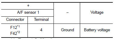
*1: Except California
*2: For California
Is the inspection result normal? YES >> GO TO 2.
NO >> Repair or replace error-detected parts.
2.CHECK A/F SENSOR 1 HEATER OUTPUT SIGNAL CIRCUIT
- Turn ignition switch OFF.
- Disconnect ECM harness connector.
- Check the continuity between A/F sensor 1 harness connector and ECM harness connector.
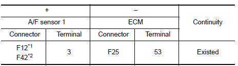
*1: Except California
*2: For California
- Also check harness for short to ground and short to power.
Is the inspection result normal? YES >> GO TO 3.
NO >> Repair open circuit, short to ground or short to power in harness or connectors.
3.CHECK A/F SENSOR 1 HEATER
Check the A/F sensor 1 heater. Refer to EC-177, "Component Inspection (A/F Sensor 1 Heater)".
Is the inspection result normal? YES >> Check intermittent incident. Refer to GI-39, "Intermittent Incident".
NO >> Replace malfunctioning air fuel ratio (A/F) sensor 1. Refer to EM-30, "Exploded View".
Component Inspection (A/F Sensor 1 Heater)
1.CHECK AIR FUEL RATIO (A/F) SENSOR 1
- Turn ignition switch OFF.
- Disconnect A/F sensor 1 harness connector.
- Check resistance between A/F sensor 1 terminals as per the following.
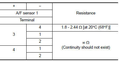
Is the inspection result normal? YES >> INSPECTION END
NO >> Replace air fuel ratio (A/F) sensor 1. Refer to EM-30, "Exploded View".
 P0014 EVT control
DTC Logic
DTC DETECTION LOGIC
NOTE:
If DTC P0014 is displayed with DTC P0078, first perform trouble
diagnosis for DTC P0078. Refer to
EC-183, "DTC Logic".
If DTC P0014 is displa ...
 P0037, P0038 HO2S2 Heater
DTC Logic
DTC DETECTION LOGIC
DTC No.
CONSULT screen terms
(Trouble diagnosis content)
DTC detecting condition
Possible cause
P0037
HO2 HTR (B1)
(HO2S heater contro ...
Other materials:
Basic inspection
Diagnosis and repair work flow
Work flow
Overall sequence
Detailed flow
1.Get information for symptom
Get the detailed information from the customer about the symptom (the
condition and the environment when
the incident/malfunction occurred) using the “diagnostic work sheet”. ( ...
Recommended chemical products and sealants
Refer to the following chart for help in selecting the appropriate chemical
product or sealant.
Product Description
Purpose
Nissan North America
Part No. (USA)
Nissan Canada Part
No. (Canada)
Aftermarket Crossreference
Part Nos.
1
Rear View Mirror ...
Rear shock absorber
Exploded View
Rear suspension beam
Shock absorber
Bound bumper
Bound bumper cover
Washer
Bushing
Distance tube
Bushing
Washer
Piston rod lock nut
Cap
Front
Removal and Installation
REMOVAL
Remove the rear shock tower access flap.
Remove the cap from the rear s ...
