Nissan Sentra Service Manual: P0014 EVT control
DTC Logic
DTC DETECTION LOGIC
NOTE:
- If DTC P0014 is displayed with DTC P0078, first perform trouble diagnosis for DTC P0078. Refer to EC-183, "DTC Logic".
- If DTC P0014 is displayed with P1078, first perform trouble diagnosis for P1078. Refer to EC-359, "DTC Logic".
| DTC No. | CONSULT screen terms (Trouble diagnosis content) | DTC detecting condition | Possible cause |
| P0014 | EXH/V TIM CONT-B1 (″B″ Camshaft position - timing over-advanced or system performance bank 1) | There is a gap between angle of target and phase-control angle degree. |
|
DTC CONFIRMATION PROCEDURE
1.PRECONDITIONING
If DTC Confirmation Procedure has been previously conducted, always perform the following procedure before conducting the next test.
- Turn ignition switch OFF and wait at least 10 seconds
- Turn ignition switch ON.
- Turn ignition switch OFF and wait at least 10 seconds.
TESTING CONDITION:
Before performing the following procedure, confirm that battery voltage is between 10 V and 16 V at idle.
>> GO TO 2.
2.PERFORM DTC CONFIRMATION PROCEDURE-1
 With CONSULT
- Turn ignition switch ON and select “DATA MONITOR” mode of “ENGINE” using CONSULT
- Start engine and warm it up to the normal operating temperature.
- Maintain the following conditions for at least 6 consecutive seconds. Hold the accelerator pedal as steady as possible.
- Let engine idle for 10 seconds.
- Check 1st trip DTC.
 With GST
Follow the procedure “With CONSULT” above.
Is 1st trip DTC detected? YES >> Proceed to EC-174, "Diagnosis Procedure" NO >> GO TO 3.
3.PERFORM DTC CONFIRMATION PROCEDURE-2
 With CONSULT
- Select “DATA MONITOR” mode of “ENGINE” using CONSULT.
- Maintain the following conditions for at least 20 consecutive seconds.
CAUTION:
Always drive at a safe speed.
- Check 1st trip DTC.
 With GST
Follow the procedure “With CONSULT” above.
Is 1st trip DTC detected? YES >> Proceed to EC-174, "Diagnosis Procedure" NO >> INSPECTION END
Diagnosis Procedure
1.CHECK OIL PRESSURE WARNING LAMP
- Start engine
- Check oil pressure warning lamp and confirm it is not illuminated.
Is oil pressure warning lamp illuminated? YES >> Check the engine oil level. Refer to LU-7, "Inspection".
NO >> GO TO 2.
2.CHECK EXHAUST VALVE TIMING CONTROL SOLENOID VALVE
Check the exhaust valve timing control solenoid valve. Refer to EC-172, "Component Inspection".
Is the inspection result normal? YES >> GO TO 3.
NO >> Replace exhaust valve timing control solenoid valve. Refer to EM-48, "Exploded View".
3.CHECK CRANKSHAFT POSITION SENSOR (POS)
Check the crankshaft position sensor (POS). Refer to EC-279, "Component Inspection [CKP Sensor (POS)]".
Is the inspection result normal? YES >> GO TO 4.
NO >> Replace crankshaft position sensor (POS). Refer to EM-33, "Exploded View".
4.CHECK EXHAUST VALVE TIMING CONTROL POSITION SENSOR
Check the exhaust valve timing control position sensor. Refer to EC-282, "Component Inspection [CMP Sensor (PHASE)]".
Is the inspection result normal? YES >> GO TO 5.
NO >> Replace exhaust valve timing control position sensor. Refer to EM-48, "Exploded View".
5.CHECK CAMSHAFT (EXH)
Check the following.
- Accumulation of debris to the signal plate of camshaft rear end
- Chipping signal plate of camshaft rear end
Is the inspection result normal? YES >> GO TO 6.
NO >> Remove debris and clean the signal plate of camshaft rear end or replace camshaft. Refer to EM-60, "Removal and Installation".
6.CHECK TIMING CHAIN INSTALLATION
Check service records for any recent repairs that may cause timing chain misaligned.
Are there any service records that may cause timing chain misaligned? YES >> Check timing chain installation. Refer to EM-49, "Removal and Installation".
NO >> GO TO 7.
7.CHECK LUBRICATION CIRCUIT
Refer to LU-7, "Inspection".
Is the inspection result normal? YES >> Check intermittent incident. Refer to GI-39, "Intermittent Incident".
NO >> Clean lubrication line.
Component Inspection
1.CHECK EXHAUST VALVE TIMING CONTROL SOLENOID VALVE-1
- Turn ignition switch OFF.
- Disconnect exhaust valve timing control solenoid valve harness connector.
- Check resistance between exhaust valve timing control solenoid valve terminals as per the following.
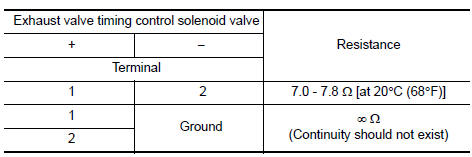
Is the inspection result normal? YES >> GO TO 2.
NO >> Replace exhaust valve timing control solenoid valve. Refer to EM-48, "Exploded View".
2.CHECK EXHAUST VALVE TIMING CONTROL SOLENOID VALVE-2
- Remove exhaust valve timing control solenoid valve. Refer to EM-48, "Exploded View".
- Provide 12 V DC between exhaust valve timing control solenoid valve terminals 1 and 2, and then interrupt it. Check that the plunger moves as shown in the figure.
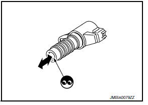
CAUTION:
Do not apply 12 V DC continuously for 5 seconds or more.
Doing so may result in damage to the coil in exhaust valve timing control solenoid valve.
NOTE:
Always replace O-ring when exhaust valve timing control solenoid valve is removed.
Is the inspection result normal? YES >> INSPECTION END
NO >> Replace exhaust valve timing control solenoid valve. Refer to EM-48, "Exploded View".
 P0011 IVT control
DTC Logic
DTC DETECTION LOGIC
NOTE:
If DTC P0011 is displayed with DTC P0075, first perform the trouble
diagnosis for EC-180, "DTC Logic".
DTC No.
CONSULT screen terms
(Tr ...
 P0031, P0032 A/F sensor 1 Heater
DTC Logic
DTC DETECTION LOGIC
DTC No.
CONSULT screen terms
(Trouble diagnosis content)
DTC detecting condition
Possible cause
P0031
A/F SEN 1 HTR (B1)
(HO2S heater ...
Other materials:
Diagnosis and repair work flow
Work Flow
OVERALL SEQUENCE
DETAILED FLOW
1.COLLECT INFORMATION FROM THE CUSTOMER
Get detailed information from the customer about the symptom
(the condition and the environment when the
incident/malfunction occurred) using the diagnostic worksheet. Refer to BRC-52,
"Diagnostic Wor ...
Interior room lamp
Removal and installation
Removal
Insert a suitable tool into the gap between the headlining and the
interior room lamp and release the interior
room lamp.
Disconnect the harness connector from the interior room lamp.
Installation
Installation is in the reverse order of removal.
Bul ...
Precaution
Precaution for Supplemental Restraint System (SRS)
"AIR BAG" and "SEAT BELT PRE-TENSIONER"
The Supplemental Restraint System such as “AIR BAG” and “SEAT BELT PRE-TENSIONER”,
used along
with a front seat belt, helps to reduce the risk or severity of injur ...
