Nissan Sentra Service Manual: Oil filter
Removal and Installation
REMOVAL
- Remove engine under cover. Refer to EXT-16, "Exploded View".
- Drain engine oil. Refer to LU-8, "Draining".
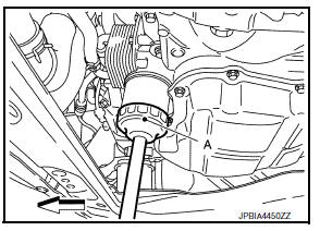
- Remove the oil filter using Tool (A) as shown.
: Front
Tool number : KV10115801 (J-38956)
WARNING:
Be careful not to burn yourself, as the engine oil may be hot.
CAUTION:
- When removing, prepare a shop cloth to absorb any oil leaks or spills.
- Do not allow engine oil to adhere to the drive belts.
- Completely wipe off any oil that adheres to the engine and the vehicle.
- The oil filter is provided with a relief valve. Use a Genuine NISSAN oil filter or equivalent.
INSTALLATION
- Remove foreign materials adhering to the oil filter installation surface.
- Apply new engine oil to the oil seal contact surface of new oil filter.
- Screw oil filter manually until it touches the installation surface, then tighten it by 2/3 turn (A), or tighten to specification.
Oil filter : 18.0 NВ·m (1.8 kg-m, 13 ft-lb)
Tool number : KV10115801 (J-38956)
- Refill engine with new engine oil. Refer to LU-9, "Refilling".
- Install engine under cover. Refer to EXT-16, "Exploded View".
Inspection
INSPECTION AFTER INSTALLATION
- Check the engine oil level. Refer to LU-7, "Inspection".
- Start the engine, and check that there are no leaks of engine oil.
- Stop the engine and wait for 10 minutes.
- Check the engine oil level, and adjust the level. Refer to LU-7, "Inspection".
 Engine oil
Inspection
Engine oil level
Note:
Before starting engine, put vehicle horizontally and check the engine oil
level. If engine is already started, stop
it and allow 10 minutes before checking.
...
 Removal and installation
OIL COOLER
Exploded View
M/T models
Clamp
Water hose
Clamp
Water hose
Oil cooler
O-rings
CVT models
Clamp
Water hose
Clamp
Water hose
Water hose clip
Oil coole ...
Other materials:
Starter motor drive control
STARTER MOTOR DRIVE CONTROL : System Description
SYSTEN DIAGRAM
*1: CVT models
*2: M/T models
INPUT/OUTPUT SIGNAL CHART
Sensor
Input signal to ECM
ECM function
Actuator
Crankshaft position sensor (POS)
Engine speed
Piston position
Starter ...
Abs branch line circuit
Diagnosis procedure
1.CHECK CONNECTOR
Turn the ignition switch OFF.
Disconnect the battery cable from the negative terminal.
Check the terminals and connectors of the ABS actuator and electric unit
(control unit) for damage, bend
and loose connection (unit side and connector side).
...
C1140 Actuator relay system
DTC Logic
DTC DETECTION LOGIC
DTC
Display Item
Malfunction detected condition
Possible causes
C1140
ACTUATOR RLY
When a malfunction is detected in actuator relay.
Harness or connector
ABS actuator and electric unit
(control unit)
Fusible link ...
