Nissan Sentra Service Manual: Moonroof switch
Description
Transmits switch operation signal to moonroof motor assembly.
Diagnosis Procedure
Regarding Wiring Diagram information, refer to RF-13, "Wiring Diagram".
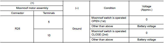
1.Check moonroof switch input signal
- Turn ignition switch on.
- Check voltage between moonroof motor assembly harness connector R26 and ground.
Is the inspection result normal? Yes >> inspection end.
No >> go to 2.
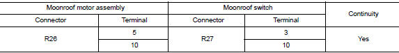
2.Check moonroof switch circuit
- Turn ignition switch OFF.
- Disconnect moonroof motor assembly connector and moonroof switch connector.
- Check continuity between moonroof motor assembly harness connector R26 and moonroof switch harness connector R27.
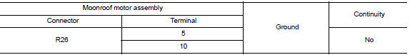
- Check continuity between moonroof motor assembly harness connector R26 and ground.
Is the inspection result normal? YES >> GO TO 3.
NO >> Repair or replace the harness or connectors.
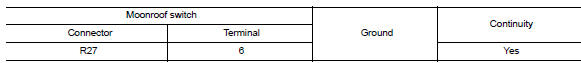
3.Check moonroof switch ground circuit
Check continuity between moonroof switch harness connector r27 and ground.
Is the inspection result normal? YES >> GO TO 4.
NO >> Repair or replace the harness or connectors.
4.Check moonroof switch
Check moonroof switch.
Refer to rf-25, "component inspection".
Is the inspection result normal? Yes >> go to 5.
No >> replace moonroof switch. Refer to rf-50, "removal and installation".
5.Check intermittent incident
Refer to gi-39, "intermittent incident".
>> Inspection end.
Component inspection
Moonroof switch
1. Check moonroof switch
- Turn ignition switch off.
- Disconnect moonroof switch.
- Check continuity between moonroof switch terminals.
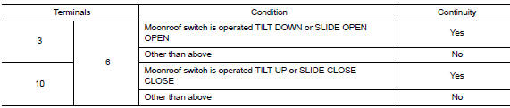
Is the inspection result normal? Yes >> moonroof switch is ok.
No >> replace moonroof switch. Refer to rf-50, "removal and installation".
 Power supply and ground circuit
Body control system
Body control system : diagnosis procedure
Regarding wiring diagram information, refer to bcs-51, "wiring diagram".
1.Check fuses and fusible link
Check that the follo ...
 Door switch
Component Function Check
1.Check function
Select DOOR LOCK of BCM using CONSULT
Select door sw-dr, door sw-as in data monitor mode
Check that the function operates normally according to the f ...
Other materials:
Air cleaner filter
Exploded View
Mass air flow sensor
Mass air flow gasket
Clamp
Air duct (suction side)
Resonator
Clamp
PCV hose
Clamp
Clamp
Air cleaner cover
Mounting rubber
Air cleaner filter
Air cleaner body
Air duct inlet (lower)
Air duct inlet (upper)
Grommet
Bracket
Gro ...
Power supply and ground circuit
Diagnosis Procedure
1.CHECK FUSE
Check that the following fuse is not fusing.
Is the fuse fusing?
YES >> Replace the fuse after repairing the applicable circuit.
NO >> GO TO 2.
2.CHECK GROUND CONNECTION
Turn ignition switch OFF
Check ground connection E9 and E15. Refer ...
U1000 CAN Comm circuit
DTC Logic
DTC DETECTION LOGIC
DTC
Display Item
Malfunction detected condition
Possible causes
U1000
CAN COMM CIRCUIT
When CAN communication signal is not continuously
received for 2 seconds or more
CAN communication system malfunction
Diagnosis Procedure
...
