Nissan Sentra Service Manual: Main line between ipdm-e and dlc circuit
Diagnosis procedure
1.Check connector
- Turn the ignition switch off.
- Disconnect the battery cable from the negative terminal.
- Check the following terminals and connectors for damage, bend and loose connection (connector side and harness side).
- Harness connector e4
- Harness connector m2
Is the inspection result normal? YES >> GO TO 2.
NO >> Repair the terminal and connector.
2.Check harness continuity (open circuit)
- Disconnect the following harness connectors.
- IPDM E/R
- Harness connectors e4 and m2
- Check the continuity between the IPDM E/R harness connector and the harness connector.
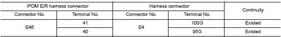
Is the inspection result normal? YES >> GO TO 3.
NO >> Repair the main line between the IPDM E/R and the harness connector E4.
3.Check harness continuity (open circuit)
Check the continuity between the harness connector and the data link connector.
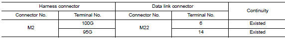
Is the inspection result normal? Yes (present error)>>check can system type decision again.
Yes (past error)>>error was detected in the main line between the ipdm e/r and the data link connector.
No >> repair the main line between the harness connector m2 and the data link connector.
 Can system (type 4)
Dtc/circuit diagnosis ...
 Main line between dlc and hvac circuit
Diagnosis Procedure
1.Check harness continuity (open circuit)
Turn the ignition switch OFF.
Disconnect the battery cable from the negative terminal.
Disconnect the following harness connector ...
Other materials:
Cooling fan
Component
Fan shroud and motor assembly
WARNING:
Do not remove the radiator cap when the engine is hot. Serious burns
could occur from high-pressure
engine coolant escaping from the radiator. Wrap a thick cloth around the cap.
Slowly push down and
turn it a quarter turn to allow b ...
Optical sensor
Description
The optical sensor measures ambient light and transmits the optical sensor
signal to the bcm.
Component function check
1.Check optical sensor signal by consult
Consult
Turn the ignition switch ON.
Select opti sen of bcm (head lamp) data monitor item.
Turn the lighting swit ...
System
Meter system
Meter system : system diagram
Meter system : system description
COMBINATION METER
The combination meter receives signals from switches, sensors and modules to
control the following functions:
Speedometer/tachometer
Warning lamps
Indicator lamps
Meter illumination c ...
