Nissan Sentra Service Manual: Main line between ipdm-e and dlc circuit
Diagnosis procedure
1.Check connector
- Turn the ignition switch off.
- Disconnect the battery cable from the negative terminal.
- Check the following terminals and connectors for damage, bend and loose connection (connector side and harness side).
- Harness connector e4
- Harness connector m2
Is the inspection result normal? Yes >> go to 2.
No >> repair the terminal and connector.
2.Check harness continuity (open circuit)
- Disconnect the following harness connectors.
- Ipdm e/r
- Harness connectors e4 and m2
- Check the continuity between the ipdm e/r harness connector and the harness connector.
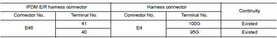
Is the inspection result normal? Yes >> go to 3.
No >> repair the main line between the ipdm e/r and the harness connector e4.
3.Check harness continuity (open circuit)
Check the continuity between the harness connector and the data link connector.
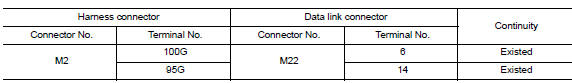
Is the inspection result normal? Yes (present error)>>check can system type decision again.
Yes (past error)>>error was detected in the main line between the ipdm e/r and the data link connector.
No >> repair the main line between the harness connector m2 and the data link connector.
 Can system (type 3)
Dtc/circuit diagnosis ...
 Main line between dlc and av circuit
Diagnosis procedure
1.Check harness continuity (open circuit)
Turn the ignition switch off.
Disconnect the battery cable from the negative terminal.
Disconnect the following harness connector ...
Other materials:
Power supply and ground circuit
Combination meter
COMBINATION METER : Diagnosis Procedure
Regarding Wiring Diagram information, refer to MWI-28, "Wiring Diagram".
1.Check fuses
Check that the following fuses are not blown.
Is the fuse blown?
Yes >> replace the blown fuse after repairing the affected circu ...
Charging system
System Diagram
System Description
The generator provides DC voltage to operate the vehicle's electrical system
and to keep the battery charged.
The voltage output is controlled by the IC regulator.
Component Description
...
F.M.V.S.S./C.M.V.S.S. certification label
The Federal/Canadian Motor Vehicle Safety
Standard (F.M.V.S.S./C.M.V.S.S.) certification label
is affixed as shown. This label contains valuable
vehicle information, such as: Gross Vehicle
Weight Ratings (GVWR), Gross Axle Weight
Rating (GAWR), month and year of manufacture,
Vehicle Identi ...
