Nissan Sentra Service Manual: M&a branch line circuit
Diagnosis procedure
1.Check connector
- Turn the ignition switch off.
- Disconnect the battery cable from the negative terminal.
- Check the terminals and connectors of the combination meter for damage, bend and loose connection (unit side and connector side).
Is the inspection result normal? Yes >> go to 2.
No >> repair the terminal and connector.
2.Check harness for open circuit
- Disconnect the connector of combination meter.
- Check the resistance between the combination meter harness connector terminals.
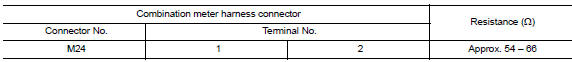
Is the measurement value within the specification? Yes >> go to 3.
No >> repair the combination meter branch line.
3.Check power supply and ground circuit
Check the power supply and the ground circuit of the combination meter. Refer to mwi-52, "combination meter : diagnosis procedure".
Is the inspection result normal? Yes (present error)>>replace the combination meter. Refer to mwi-77, "removal and installation".
Yes (past error)>>error was detected in the combination meter branch line.
No >> repair the power supply and the ground circuit.
 Eps branch line circuit
Diagnosis procedure
1.Check connector
Turn the ignition switch off.
Disconnect the battery cable from the negative terminal.
Check the terminals and connectors of the eps control unit for dam ...
 Strg branch line circuit
Diagnosis Procedure
1.Check connector
Turn the ignition switch off
Disconnect the battery cable from the negative terminal.
Check the terminals and connectors of the steering angle sensor for ...
Other materials:
Rear-facing child restraint installation using the seat belts
WARNINGThe three-point seat belt with Automatic
Locking Retractor (ALR) must be used
when installing a child restraint. Failure to
use the ALR mode will result in the child
restraint not being properly secured. The
restraint could tip over or be loose and
cause injury to ...
P1651 Starter motor relay
Description
ECM controls ON/OFF state of the starter relay, according to the engine and
vehicle condition. ECM transmits
a control signal to IPDM E/R by CAN communication.
Under normal conditions, ECM controls and maintains the starter relay in OFF
state during following condition:
Engi ...
Basic inspection
Diagnosis and repair work flow
Work flow
Overall sequence
Detailed flow
1.Get information for symptom
Get the detailed information from the customer about the symptom (the
condition and the environment when
the incident/malfunction occurred) using the “diagnostic work sheet”. ( ...
