Nissan Sentra Service Manual: L terminal circuit (short)
Description
The terminal “l” circuit controls the charge warning lamp. The charge warning lamp turns on when the ignition switch is set to on or start. When the generator is providing sufficient voltage with the engine running, the charge warning lamp turns off. If the charge warning lamp illuminates with the engine running, a malfunction is indicated.
Diagnosis Procedure
Regarding wiring diagram information, refer to chg-9, "wiring diagram".
1.Check “l” terminal circuit (short)
- Turn ignition switch off.
- Disconnect generator connector.
- Turn ignition switch on.
Does charge warning lamp illuminate? YES >> GO TO 2.
NO >> Refer to CHG-14, "Work Flow (With EXP-800 NI or GR8-1200 NI)" or CHG-17, "Work Flow (Without EXP-800 NI or GR8-1200 NI)".
2.Check harness continuity (short circuit)
- Turn ignition switch off.
- Disconnect the battery cable from the negative terminal.
- Disconnect combination meter connector.
- Check continuity between the combination meter harness connector and ground.
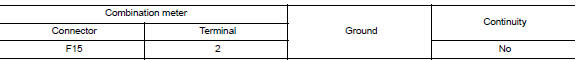
Is the inspection result normal? Yes >> replace the combination meter. Refer to mwi-77, "removal and installation".
No >> repair or replace the harness or connectors.
 L terminal circuit (open)
Description
The “L” terminal circuit controls the charge warning lamp. The charge warning
lamp turns ON when the ignition
switch is set to ON or START. When the generator is providing su ...
 S terminal circuit
Description
The output voltage of the generator is controlled by the IC regulator at
terminal “S” detecting the input voltage
from battery.
The “S” terminal circuit detects ...
Other materials:
U0155 Lost communication (IPC)
DTC Logic
DTC DETECTION LOGIC
DTC
CONSULT screen terms
[Trouble diagnosis content]
DTC detection condition
Possible causes
U0155
LOST COMM (IPC)
[Lost Communication With Instrument
Panel Cluster (IPC)
Control Module]
When the ignition switch is ON, TCM is ...
Ecu diagnosis information
Ipdm e/r (intelligent power distribution module engine room)
Reference Value
Values on the diagnosis tool
Terminal layout
Physical values
Fail-Safe
Can communication control
When can communication with ecm and bcm is impossible, ipdm e/r performs
fail-safe ...
Front disc brake
Brake Burnishing
CAUTION:
Burnish contact surfaces between brake pads and disc rotor
according to the following procedure
after refinishing the disc rotor, replacing brake pads or if a soft pedal
occurs at very low mileage.
Be careful of vehicle speed. Brakes do not operate firmly/sec ...
