Nissan Sentra Service Manual: Intake manifold runner control
INTAKE MANIFOLD RUNNER CONTROL : System Description
SYSTEM DIAGRAM
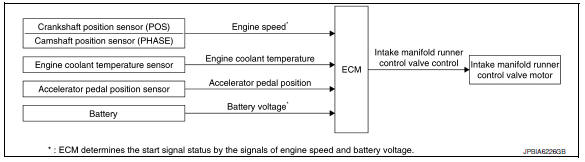
SYSTEM DESCRIPTION
Intake manifold runner control valve has a valve portion in the intake passage of each cylinder.
While idling and during low engine coolant temperature, the intake manifold runner control valve closes. Thus the velocity of the air in the intake passage increases, promoting the vaporization of the fuel and producing a intake manifold runner in the combustion chamber.
Because of this operation, this system tends to increase the burning speed of the gas mixture, improve exhaust emission, and increase the stability in running conditions.
Also, except when idling and during low engine coolant temperature, this system opens the intake manifold runner control valve.
In this condition, this system tends to increase power by improving intake efficiency via reduction of intake flow resistance.
The intake manifold runner control valve is operated by the ECM.
 Exhaust valve timing control
EXHAUST VALVE TIMING CONTROL : System
Description
SYSTEM DIAGRAM
INPUT/OUTPUT SIGNAL CHART
Sensor
Input signal to ECM
ECM function
Actuator
Crankshaft position sensor ...
 Intake manifold tuning system
INTAKE MANIFOLD TUNING SYSTEM : System
Description
SYSTEM DIAGRAM
SYSTEM DESCRIPTION
This system switches the length of intake air path according to the
low-to-medium speed range or high spe ...
Other materials:
Precaution
Precaution for supplemental restraint system (srs) "air bag" and "seat
belt pre-tensioner"
The supplemental restraint system such as “air bag” and “seat belt pre-tensioner”,
used along
with a front seat belt, helps to reduce the risk or severity of injur ...
Basic inspection
Diagnosis and repair workflow
Work flow
Overall sequence
Detailed flow
1.Get information for symptom
Get detailed information from the customer about the symptom (the condition
and the environment when the
incident/malfunction occurred).
>> Go to 2
2.Confirm the symptom
Try to ...
Wiring diagram
Display audio without bose
Wiring diagram
...
