Nissan Sentra Service Manual: Illumination control switch signal circuit
Diagnosis procedure
Regarding wiring diagram information, refer to mwi-28, "wiring diagram".
1.Check combination meter input signal
- Turn ignition switch on.
- Check voltage between the following terminals of the illumination control switch.
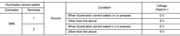
Is the inspection result normal? YES >> Inspection End.
NO >> GO TO 2.
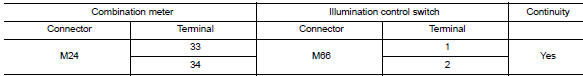
2.Check illumination control switch signal circuit
- Turn ignition switch off
- Disconnect combination meter connector m24 and illumination control switch connector m66.
- Check continuity between combination meter harness connector and illumination control switch harness connector.
- Check continuity between combination meter harness connector and ground.
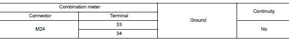
Is the inspection result normal? Yes >> check illumination control switch. Refer to mwi-56, "component inspection".
No >> repair or replace harness or connector.
Component inspection
1.Check illumination control switch
- Turn ignition switch OFF.
- Disconnect illumination control switch connector.
- Check illumination control switch.
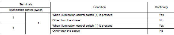
Is the inspection result normal? Yes >> inspection end.
No >> replace illumination control switch. Refer to mwi-80, "removal and installation".
 Steering switch (meter control switch) signal circuit
Diagnosis Procedure
Regarding wiring diagram information, refer to mwi-28, "wiring diagram".
1.Check combination meter input signal
Turn ignition switch on.
Measure voltage between ...
 Fuel level sensor signal circuit
Description
The fuel level sensor unit and fuel pump detects the approximate fuel level
in the fuel tank and transmits the
fuel level signal to the combination meter.
Component function check
1 ...
Other materials:
Overdrive control switch
Component Function Check
1.CHECK SPORT INDICATOR LAMP FUNCTION
Check OD OFF indicator lamp turns ON for approx. 2 seconds when ignition
switch turns ON.
Is the inspection result normal?
YES >> GO TO 2.
NO >> Go to TM-239, "Diagnosis Procedure".
2.CHECK SPORT MODE SW ...
Preparation
Special service tools
The actual shape of the tools may differ from those illustrated here.
Commercial service tools
Clip list
Descriptions for Clips
Replace any clips which are damaged during removal or installation.
...
System description
Component parts
Component parts location
Ipdm e/r (contains ignition relay-1)
Bcm (view with instrument panel removed)
Fuse block (j/b) (front)
Fuse block (j/b) (back)
Blower relay
Ignition relay-2
Accessory relay-1
Push-button ignition switch
Component description
...
