Nissan Sentra Service Manual: G Sensor
Exploded View
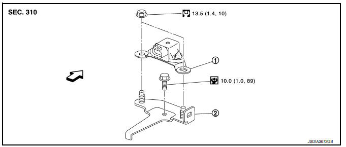
- G sensor
- Bracket
 Vehicle front
 NВ·m (kg-m, ft-lb)
 NВ·m (kg-m, in-lb)
Removal and Installation
WARNING:
Do not leave any objects (screwdrivers, tools, etc.) on the seat during seat repair. It can lead to personal injury if the side air bag module should accidentally deploy.
CAUTION:
- Do not drop or strike G sensor, because it has little tolerance for impact.
- Do not use a power tool and avoid impact.
REMOVAL
- Disconnect the negative and positive battery terminals and wait at least three minutes. Refer to PG-50, "Removal and Installation (Battery)".
- Remove driver seat. Refer to SE-18, "DRIVER SIDE : Removal and Installation - Seat Assembly".
- Remove center pillar lower garnish (left side) and dash side finisher (left side). Refer to INT-27, "CENTER PILLAR LOWER FINISHER : Removal and Installation" (center pillar lower garnish) and INT-26, "DASH SIDE FINISHER : Removal and Installation" (dash side finisher).
- Pull up floor carpet. Refer to INT-35, "Removal and Installation".
- Disconnect G sensor harness connector.
- Remove G sensor.
- Remove bracket.
INSTALLATION
Installation is the reverse order of removal.
Adjustment
ADJUSTMENT AFTER INSTALLATION
Perform “CALIBRATION OF G SENSOR”. Refer to TM-147, "Description".
 AIR Breather hose
Exploded View
Harness bracket
Clip
Air breather hose
Vehicle front
Always replace after every
disassembly.
Removal and Installation
REMOVAL
Remove clips from harness bracke ...
 OIL PAN
Exploded View
Transaxle assembly
Oil pan gasket
Magnet
Oil pan
Overflow tube
Drain plug gasket
Drain plug
Oil pan fitting bolt
: Always replace after every
disassembly.
: ...
Other materials:
B0098 Front door satellite sensor RH
Description
DTC B0098 FRONT DOOR SATELLITE SENSOR RH
The front door satellite sensor RH is wired to the air bag diagnosis sensor
unit. The air bag diagnosis sensor
unit will monitor the front door satellite sensor RH for internal failures and
its circuits for communication errors.
PART LOCA ...
Precaution for Supplemental Restraint System (SRS) "AIR BAG" and "SEAT
BELT PRE-TENSIONER"
The Supplemental Restraint System such as “AIR BAG” and “SEAT BELT PRE-TENSIONER”,
used along
with a front seat belt, helps to reduce the risk or severity of injury to the
driver and front passenger for certain
types of collision. Information necessary to service the system ...
NISSAN Intelligent Key® (if so equipped)
WARNING
Radio waves could adversely affect
electric medical equipment. Those who
use a pacemaker should contact the
electric medical equipment manufacturer
for the possible influences before
use.
The Intelligent Key transmits radio
waves when the buttons are pr ...
