Nissan Sentra Service Manual: Fuel level sensor signal circuit
Description
The fuel level sensor unit and fuel pump detects the approximate fuel level in the fuel tank and transmits the fuel level signal to the combination meter.
Component function check
1.Combination meter input signal
- Select meter/m&a on consult.
- Using FUEL METER of DATA MONITOR, compare the value of DATA MONITOR with fuel gauge pointer of combination meter.
Does the data monitor value approximately match the fuel gauge indication? YES >> Inspection End.
NO >> Replace combination meter. Refer to MWI-77, "Removal and Installation".
Diagnosis procedure
Regarding wiring diagram information, refer to mwi-28, "wiring diagram".
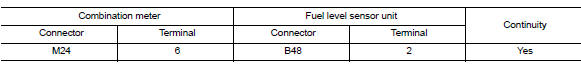
1.Check fuel level sensor circuit
- Turn ignition switch off.
- Disconnect combination meter connector and fuel level sensor unit connector.
- Check continuity between combination meter harness connector and fuel level sensor unit harness connector.
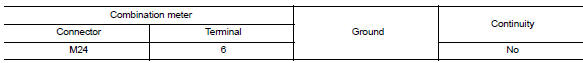
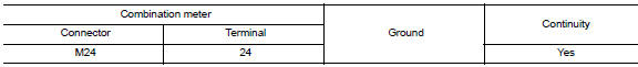
- Check continuity between combination meter harness connector and ground.
Is the inspection result normal? Yes >> go to 2.
No >> repair or replace harness or connector.
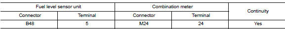
2.Check fuel level sensor ground circuit
- Check continuity between fuel level sensor unit harness connector and combination meter harness connector.
- Check continuity between combination meter harness connector and ground.
Is the inspection result normal? YES >> GO TO 3.
NO >> Repair or replace harness or connector.
3.Check installation condition
Check fuel level sensor unit installation, and check whether the float arm interferes or binds with any of the internal components in the fuel tank.
Is the inspection result normal? Yes >> inspection end.
No >> install the fuel level sensor unit properly. Refer to fl-6, "removal and installation".
Component inspection
1.Remove fuel level sensor unit
Remove the fuel level sensor unit. Refer to fl-6, "removal and installation".
>> Go to 2.
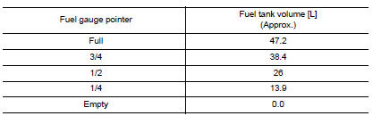
2.Check fuel level sensor unit
Check the resistance between fuel level sensor unit and fuel pump.
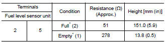
*: When float rod is in contact with stopper.
Is inspection result ok? Yes >> inspection end.
No >> replace fuel level sensor unit and fuel pump. Refer to fl-6, "removal and installation".
 Illumination control switch signal circuit
Diagnosis procedure
Regarding wiring diagram information, refer to mwi-28, "wiring diagram".
1.Check combination meter input signal
Turn ignition switch on.
Check voltage between the ...
 Parking brake switch signal circuit
Component function check
1.Check parking brake switch operation
Check that brake warning lamp in combination meter turns on/off when parking
brake is actuated.
Is the inspection result normal?
...
Other materials:
P0171 Fuel injection system function
DTC Logic
DTC DETECTION LOGIC
With the Air/Fuel Mixture Ratio Self-Learning Control, the actual mixture
ratio can be brought closely to the
theoretical mixture ratio based on the mixture ratio feedback signal from the
A/F sensors 1. The ECM calculates
the necessary compensation to correct th ...
Exhaust manifold
Exploded View
CALIFORNIA
Air fuel ratio sensor
Exhaust manifold heat shield (upper)
Exhaust manifold and three way catalyst
Exhaust manifold heat shield (rear)
Exhaust manifold heat shield (front)
Exhaust manifold gasket
Cylinder head
EXCEPT CALIFORNIA
Air fuel ratio ...
P285A Clutch B Pressure
DTC Logic
DTC DETECTION LOGIC
DTC
CONSULT screen terms
(Trouble diagnosis content)
DTC detection condition
Possible causes
P285A
CLUTCH B PRESSURE
(Clutch B Pressure Disengagement
Performance)
The detection conditions continuously for 200
msec or more und ...
