Nissan Sentra Service Manual: Front combination lamp
Exploded view
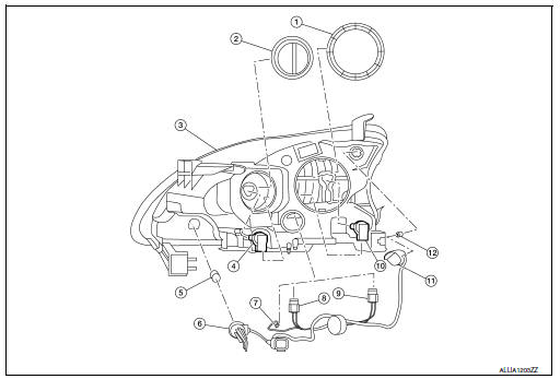
- Large cover (not serviceable)
- Small cover (not serviceable)
- Front combination lamp
- Halogen lamp bulb (high beam)
- Turn signal lamp bulb
- Turn signal lamp bulb socket
- LED harness connector
- Halogen lamp bulb (high beam) harness connector
- Halogen lamp bulb (low beam) harness connector
- Halogen lamp bulb (low beam)
- Side marker lamp bulb socket
- Side marker lamp bulb
Removal and installation
REMOVAL
- Remove the front bumper fascia. Refer to EXT-17, "Removal and Installation".
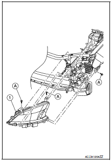
- Remove the front combination lamp bolts (A).
- Pull the front combination lamp (1) forward.
- Disconnect the harness connectors from the front combination lamp (1).
INSTALLATION
Installation is in the reverse order of removal.
After installation, perform headlamp aiming adjustment. Refer to EXL-115, "Aiming Adjustment".
Bulb replacement
WARNING:
Do not touch bulb by hand while it is lit or right after being turned off. Burning may result.
CAUTION:
- Do not touch glass surface of the bulb with bare hands or allow oil or grease to get on it to prevent damage to bulb.
- Do not leave the bulb out of the lamp reflector for a long time
because dust, moisture, smoke, etc.
may affect the performance of the lamp.
HEADLAMP HIGH BEAM
Removal
- Remove the core support cover. Refer to EXT-23, "Exploded View".
- Rotate the plastic cover counterclockwise and remove.
- Rotate the headlamp high beam lamp counterclockwise and remove.
- Disconnect the harness connector from the headlamp high beam lamp.
Installation
Installation is in the reverse order of removal.
CAUTION:
After installing, be sure to install the cover securely to ensure watertightness.
HEADLAMP LOW BEAM
Removal
- Remove the core support cover. Refer to EXT-23, "Exploded View".
- Rotate the plastic cover counterclockwise and remove.
- Rotate the headlamp low beam sockets counterclockwise and remove.
- Disconnect the harness connector from the headlamp low beam lamp.
Installation
Installation is in the reverse order of removal.
CAUTION:
After installing, be sure to install the cover securely to ensure watertightness.
SIDE MARKER LAMP
Removal
- Remove the core support cover. Refer to EXT-23, "Exploded View".
- Rotate the side marker lamp bulb socket counterclockwise and remove.
- Remove the side marker bulb from the side marker bulb socket.
Installation
Installation is in the reverse order of removal.
CAUTION:
After installing, be sure to install the bulb socket securely to ensure watertightness.
TURN SIGNAL LAMP
Removal
- Remove the core support cover. Refer to EXT-23, "Exploded View".
- Rotate the turn signal lamp bulb socket counterclockwise and remove.
- Remove the turn signal bulb from the turn signal bulb socket.
Installation
Installation is in the reverse order of removal.
CAUTION:
After installing, be sure to install the bulb socket securely to ensure watertightness.
Park Lamp
The park lamp LED bulb is integrated into the front combination lamp and is serviced as an assembly. Refer to EXL-119, "Removal and Installation".

 Front fog lamp
Removal and Installation
FOG LAMP
Removal
Position the fender protector aside. Refer to EXT-28, "FENDER PROTECTOR
: Removal and Installation
- Front Fender Protector".
Disconnec ...
Other materials:
Cylinder block
Exploded View
Cylinder block
Block heater (for Canada)
Top ring
Second ring
Oil ring
Piston
Piston pin
Snap ring
Connecting rod
Connecting rod bearing (upper)
Connecting rod bearing (lower)
Crankshaft key
Connecting rod cap
Connecting rod cap bolt
Main bearing ca ...
Unit removal and installation
TRANSAXLE ASSEMBLY
Exploded View
Transaxle assembly
Refer to INSTALLATION
Removal and Installation
WARNING:
Do not remove the radiator cap when the engine is hot. Serious burns
could occur from high pressure
coolant escaping from the radiator. Wrap a thick cloth around the cap. ...
During a call
While a call is active, press the
button to
access additional options. Speak one of the following
commands:
“(numbers)” – Speak numbers and then say
“Send” or say “Correction” to change the
numbers entered.
“Mute On” or “Mute Off” – Speak the command
to mute ...
